Eureka AIR delivers breakthrough ideas for toughest innovation challenges, trusted by R&D personnel around the world.

Transport system

Inactive Publication Date: 2012-06-28
WESTRICK LUDGER
View PDF11 Cites 2 Cited by
  • Summary
  • Abstract
  • Description
  • Claims
  • Application Information

AI Technical Summary

Benefits of technology

[0006]The present invention, therefore, aims at creating a transport system of the aforementioned type, which obviates the drawbacks disclosed above and in which the cargo can be safely fixed on the loading floors and are easily accessible at the same time and the loading floors can be easily handled and arranged in the loading frame in a safe and space-saving manner.

Problems solved by technology

However, this is relatively troublesome because this modification must be made inside the cargo area body which has possibly already been loaded in part because stations were approached before.
To achieve this, he needs ample access to the individual pieces of the cargo, with the result that a close arrangement of levels to allow optimal space utilization is impossible.
If close loading is aimed at, there is, therefore, the risk that the cargo is secured only inadequately in careless manner due to poor accessibility.
Since there are not enough possibilities to secure the inserted pallets or loading floors, however, this shelf pallet is not suitable as a transport system for a transport vehicle.
However, the aforementioned drawbacks are also found here because the cargo must be secured in the vehicle, for example, by fixing pallets with cargo securing beams that are extending in transverse and longitudinal directions and must be mounted manually.
According to experience, this is connected with a high risk of errors which is proved in practice by the often negative results of goods traffic controls.

Method used


Image

  • Transport system
  • Transport system
  • Transport system

Examples


Embodiment Construction

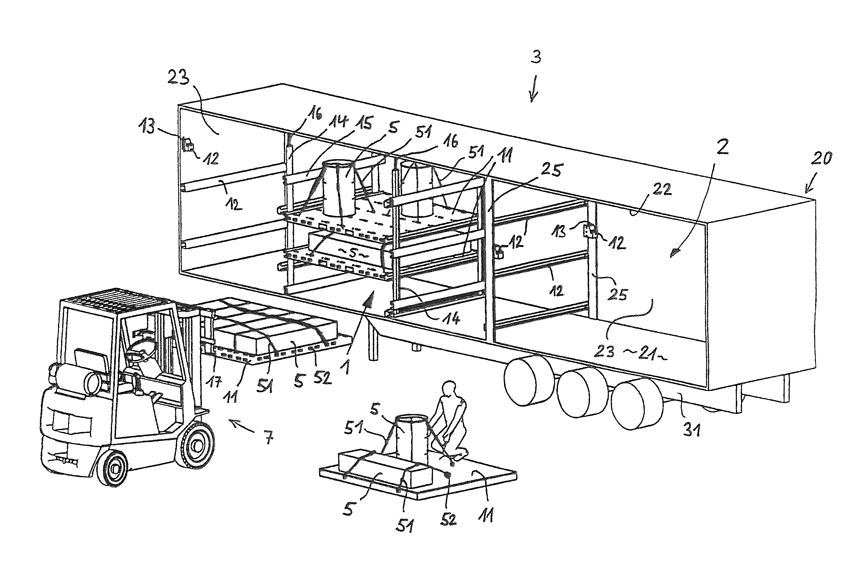
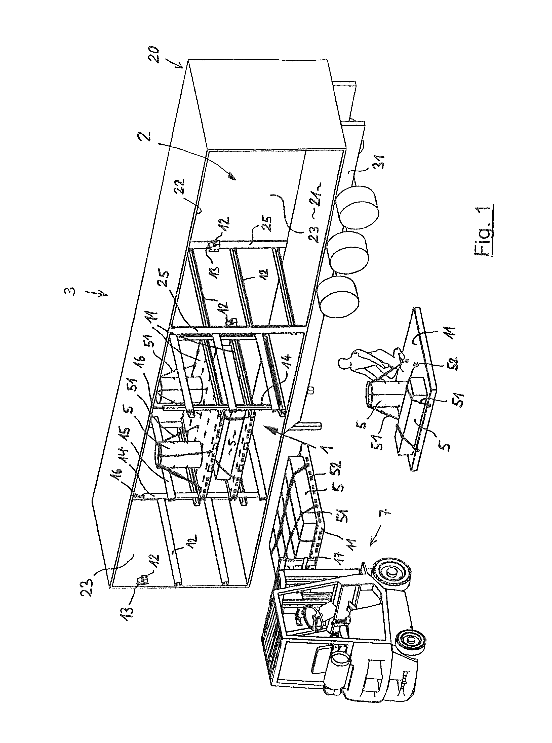
[0062]FIG. 1 is a schematic view of a loading process of a transport vehicle 3 that is equipped with the transport system according to the invention described above, shown with a road semitrailer in the illustrated instance, the cargo area body 20 of which has a cargo area 2 and is opened on its side for loading. The transport vehicle 3 has a vehicle frame 31 on which rests a cargo area floor 21. Cargo area walls 23 the side wall of which that is facing the viewer is opened or removed in the illustrated instance are provided on the lateral and front sides. At its upper side, the cargo area 23 is closed by a cargo area ceiling 22.

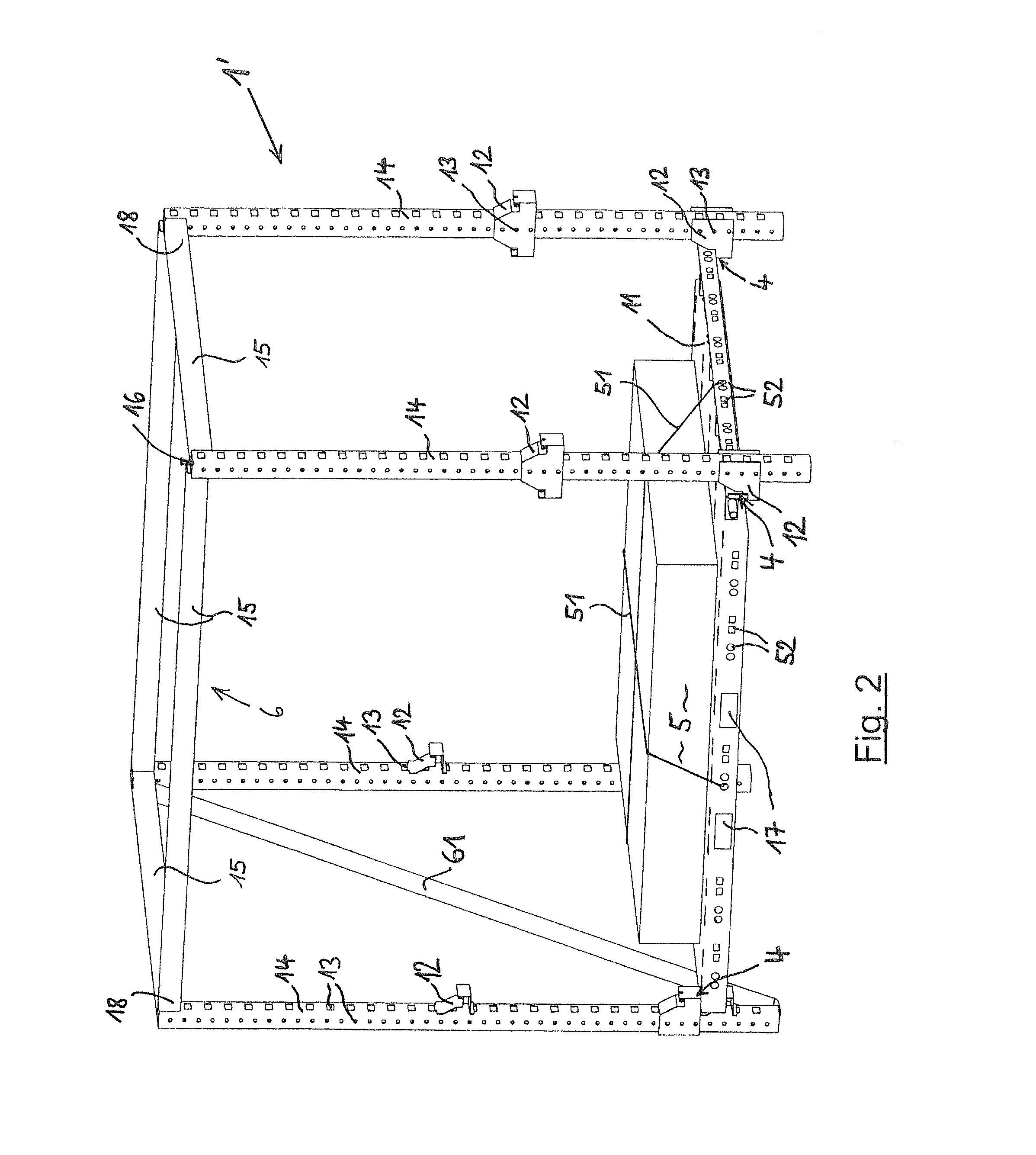
[0063]In this example, a loading frame 1 is arranged in the cargo area 2, said loading frame 1 having three partial loading frames with different designs to show different embodiments; in practice, a transport vehicle 3, appropriately, has uniform partial loading frames. In the illustrated instance, two loading floors 11 have already been inserted into the l...


PUM


Abstract

A transport system having a loading frame disposed in or placeable in a cargo area of a transport vehicle and at least one loading floor that is insertable in the loading frame and removable from the loading frame. The loading frame includes posts and floor supports mounted thereon for receiving the loading floor. The transport system includes a locking system having interacting locking elements for securely and releaseably locking the loading floor for transport in the loading frame on the floor supports and / or posts and on each or the loading floor. The loading floor includes a fastening arrangement for at least one cargo securing apparatus for securing cargo to be transported on the loading floor. The cargo can be placed on the loading floor outside of the cargo area and can be fixed by the cargo securing apparatus for transport before the loading floor is placed in the loading frame.

Description

BACKGROUND OF THE INVENTION[0001]The invention relates to a transport system having a loading frame disposed in or that can be brought into a cargo area of a transport vehicle and at least one loading floor that can be inserted in the loading frame and removed from the loading frame, wherein the loading frame comprises posts and floor supports mounted thereon for receiving the at least one loading floor.[0002]A transport system of the aforementioned type is generally known as multi-level loading system in the transport of goods with transport vehicles. According to the known prior art, a plurality of loading floors are, therein, arranged one on top of the other in rack-like loading frames inside the cargo area body, in order to reach a volume utilization for general cargo transport that is as full as possible. However, the type and size of the general cargo to be transported may vary considerably, above all in line operation. To compensate for this, the known multi-level loading sys...

Claims


Application Information

Patent Timeline
IPC IPC(8): B60P1/64B60P7/06
CPCB60P1/00
Inventor WESTRICK, LUDGER
Owner WESTRICK LUDGER
Why Eureka
Eureka Blog
Learn More