Mechanical broadhead

a broadhead and mechanical technology, applied in the field of mechanical broadheads, can solve the problems of less energy remaining for target penetration, less kinetic energy, and inability to move smoothly within, and achieve the effect of reducing the complexity of mechanical broadheads and larger cutting diameters

Active Publication Date: 2012-06-28
GRACE ENG
View PDF7 Cites 35 Cited by
  • Summary
  • Abstract
  • Description
  • Claims
  • Application Information

AI Technical Summary

Benefits of technology

[0008]A mechanical broadhead including rearwardly deploying and/or sliding blades is provided. The broadhead includes a ferrule defining one or more ferrule slots, blades which are disposed and move within the slots, and a common connector body, such as a carriage element or a pin, connecti

Problems solved by technology

Pivoting blade broadheads, however, require substantial kinetic energy for blade rotation, which results in less energy remaining for target penetration

Method used


Image

  • Mechanical broadhead
  • Mechanical broadhead
  • Mechanical broadhead

Examples


first alternative embodiment

[0104]A first alternative embodiment of the broadhead is illustrated in FIGS. 11-18 and generally designated 110. This embodiment is similar to the above embodiment in structure and operation with several exceptions. For example, the ferrule body 120 can be joined with a detachable stem 130, and blades 140 can be joined with the ferrule via connector body 150. As shown in FIG. 12, however, the connector body 150 can be a generally cylindrical body, including, for example, a partially circular cross section. Of course, if desired, the cross section of the connector body 150 can be of other geometric shapes, for example, it can be square, rectangular, elliptical, polygonal or of other shapes.

[0105]The major diameter or dimension of the connector body 150 can be sized to fit within the bore 124 defined by the ferrule body 120. Optionally, the inner dimension or diameter of the bore 124 can be slightly greater than the dimensions or circumference of the external surface 151 of the conne...

second alternative embodiment

[0111]A second alternative embodiment of the broadhead is illustrated in FIGS. 19-23 and generally designated 210. This embodiment is similar to the above embodiment in structure and operation with several exceptions. For example, the broadhead generally includes a ferrule body 230 that is joined with a penetrating tip 220, and that slidably houses a connector body 250. Optionally, the blades and the retainer element, such as a blade retention clip (not shown) used in this second alternative embodiment can be similar to those of the first alternative embodiment.

[0112]As described above, the ferrule 120 of the first alternative embodiment can be configured so the blades 140 and the connector body 150 can be slidably inserted in the ferrule 120. The ferrule 120 can be joined with a detachable stem portion 130 to facilitate assembly of this first alternative embodiment. As shown in FIGS. 19-22, however, the second alternative embodiment 210, includes a ferrule and stem that form an int...

third alternative embodiment

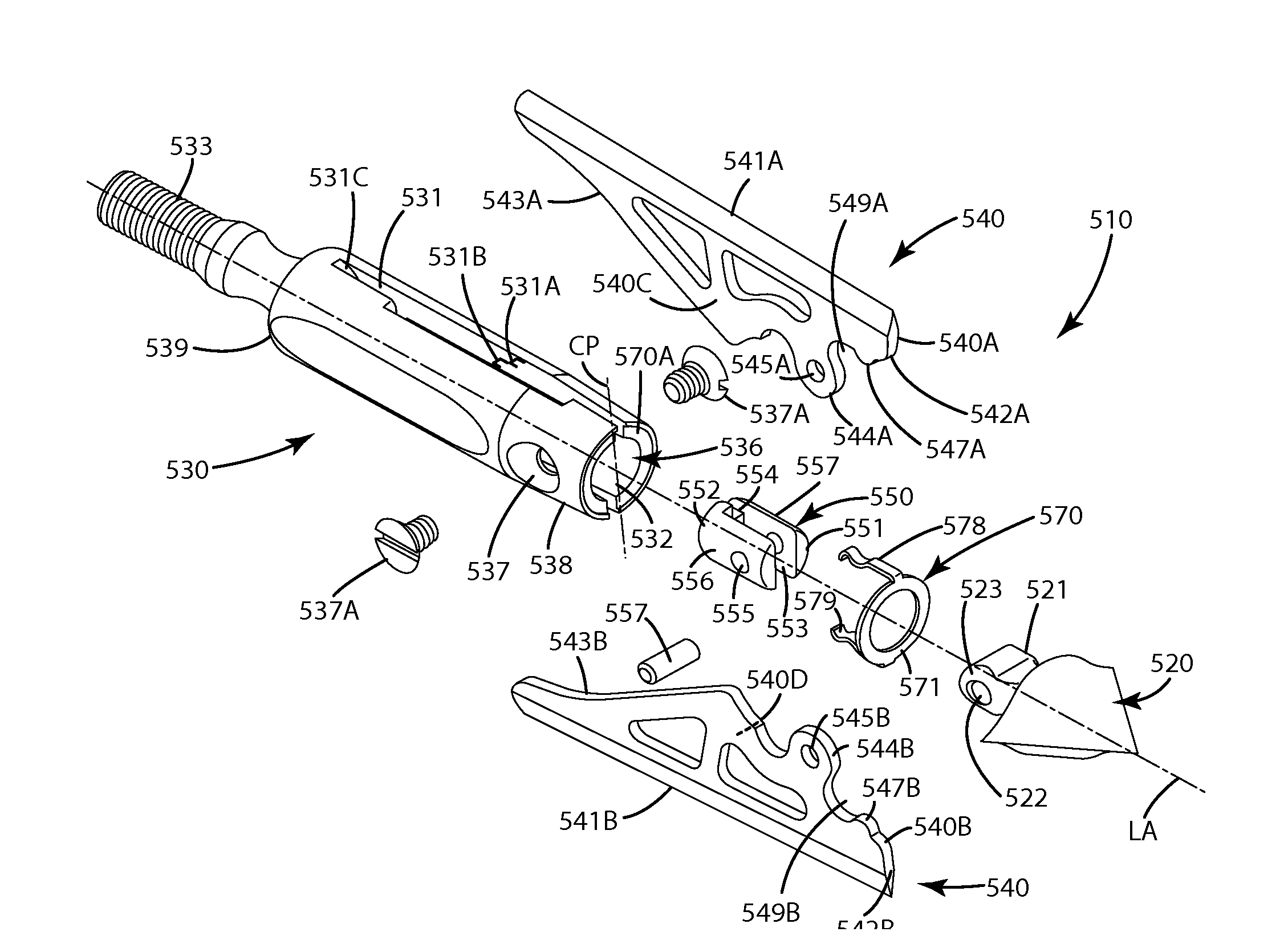
[0118]A third alternative embodiment of the broadhead is illustrated in FIGS. 25-44 and generally designated 310. This embodiment is similar to the above embodiments in structure and operation with several exceptions. For example, the broadhead generally includes a ferrule body 330 that is detachably joined with a penetrating tip 320 and that slidably houses a connector body 350. The connector body 350 can be joined with blades 340 which are adapted to deploy from a retracted mode shown in FIG. 25 to a deployed mode shown in FIG. 33.

[0119]The broadhead 310 generally includes a penetrating tip 320 which can be either a simple conical tip or trocar tip, or can be of a construction including sharpened blades as shown in FIGS. 33-37. In FIGS. 25-28, the tip 320 can include fins 321 that extend outward and rearward from a primary tip body 322. These fins can be configured and dimensioned to fit within the respective ferrule slots 331 defined by the ferrule 330. The fins can be further co...


PUM


Abstract

A mechanical broadhead including rearwardly deploying and/or sliding blades. The broadhead includes a ferrule defining a bore joined with a penetrating tip. A connector body, such as a carriage element or a pin, is slidably and moveably disposed within the bore, distal from the tip. One or more cutting blades is joined with the connector body. The connector body moves together in unison with the cutting blades as they expand from a retracted, in flight mode to a deployed, target penetrating mode. The connector body and blades can be joined with the ferrule so that the broadhead converts from a deployed mode to an unbarbed mode to facilitate broadhead removal. Optionally, the broadhead can include an internal retainer element that is resilient and durable enough to be used for multiple deployments. A related method of operating the broadhead also is provided.

Description

BACKGROUND OF THE INVENTION[0001]The present invention relates generally to a mechanical broadhead, and more particularly, to a mechanical broadhead including rearward deploying and / or sliding blades.[0002]A mechanical broadhead, sometimes referred to as an expanding blade broadhead, includes blades joined with a ferrule so that the blades can move from a retracted in-flight position to a deployed on-impact position. Mechanical broadheads generally have the flight characteristics of a field point, yet the penetration and cutting characteristics of a fixed blade broadhead.[0003]One type of mechanical broadhead is a pivoting blade broadhead. This broadhead includes blades located in a slot defined by a ferrule so that the cutting edges of the blades face inward in the retracted, in-flight position. The blades are pivotally joined with the ferrule at their rear so they can rotate from the retracted, in-flight position to a deployed position on impact with the target. In the deployed po...

Claims


Application Information

Patent Timeline
IPC IPC(8): F42B6/08
CPCF42B6/08
Inventor GRACE, NATHANIEL E.
Owner GRACE ENG
Why Eureka
Try Eureka