Method of locating hydraulic barriers within a geological gas storage layer

Inactive Publication Date: 2012-06-28
INST FR DU PETROLE
View PDF5 Cites 8 Cited by
  • Summary
  • Abstract
  • Description
  • Claims
  • Application Information

AI Technical Summary

Benefits of technology

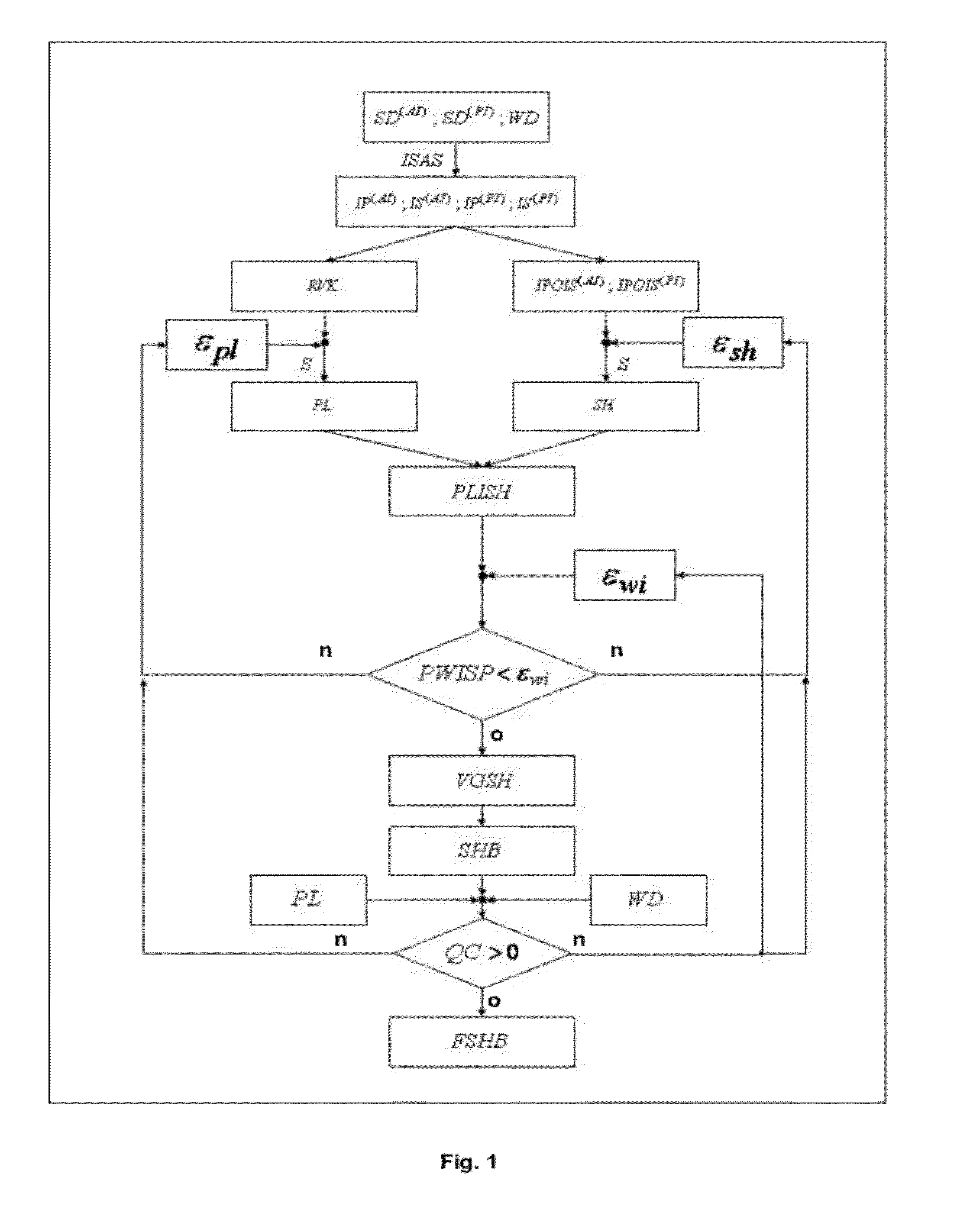
[0021]According to the invention, at least one of the thresholds can be modified upon each

Problems solved by technology

However, the evolution of the CO2 once injected is much more difficult to control.
These conventional methods are based on the use of an elastic model of the porous medium for which estimation of key parameters (drained bulk and shear moduli notably, and

Method used


Image

  • Method of locating hydraulic barriers within a geological gas storage layer
  • Method of locating hydraulic barriers within a geological gas storage layer
  • Method of locating hydraulic barriers within a geological gas storage layer

Examples


Example

[0035]The method according to the invention allows location of argillaceous zones present in a geological layer into which a gas has been injected.

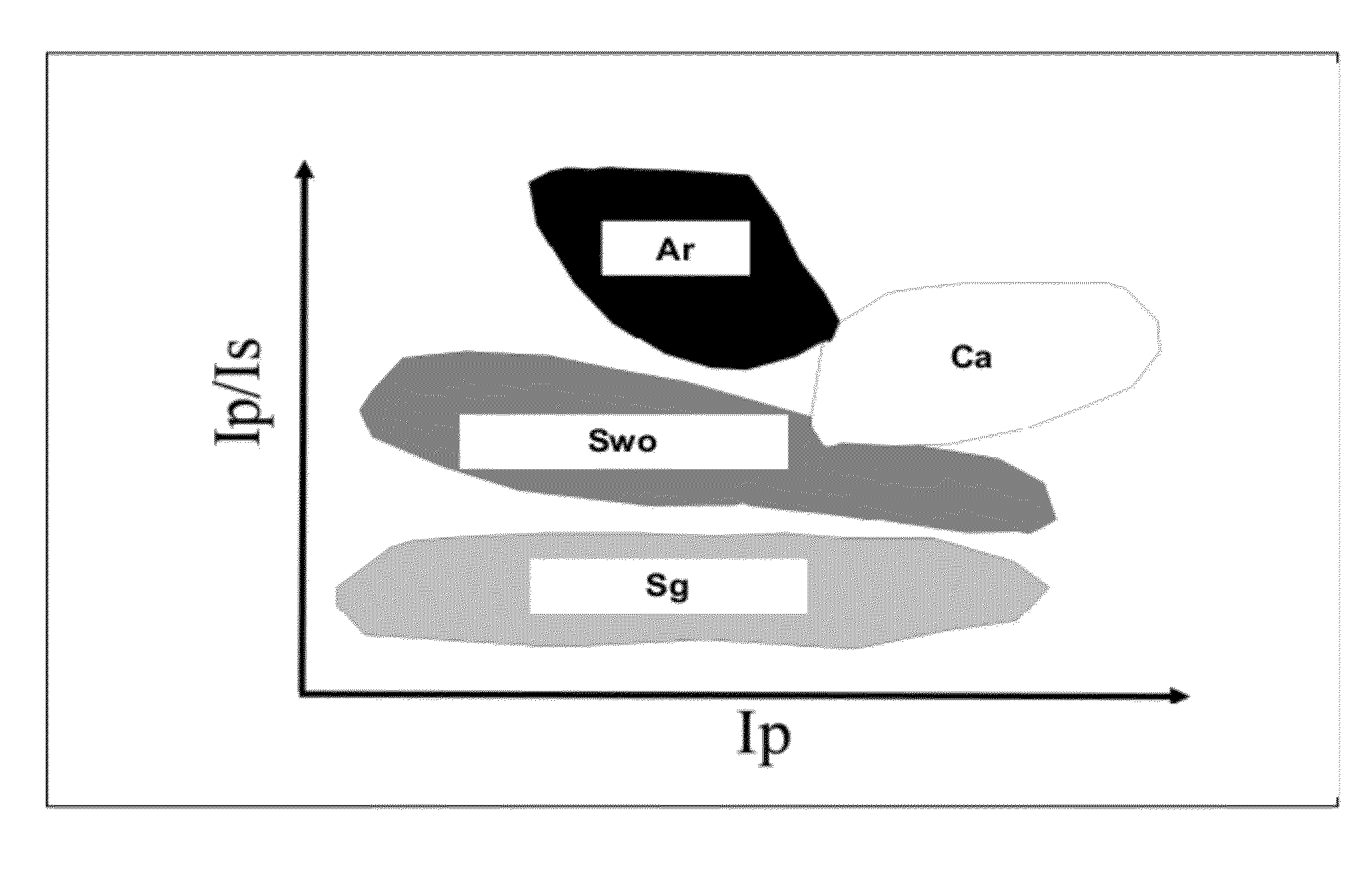
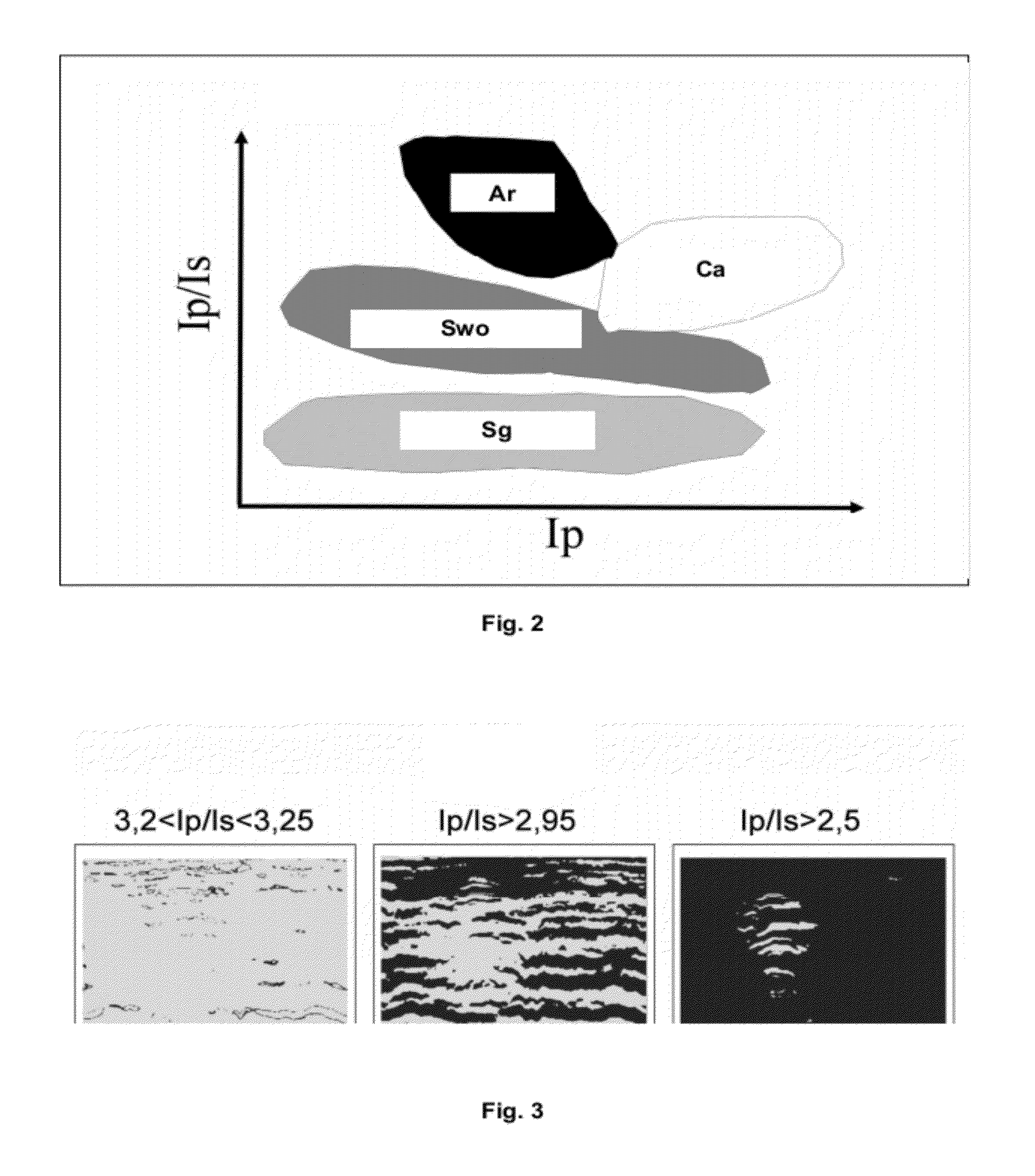
[0036]What is referred to herein as an argillaceous zone is a zone whose ratio of P wave seismic impedance (Ip) to S wave seismic impedance (Is) is greater than the ratio of these impedances in the gas storage layer. FIG. 2 illustrates the relationships between impedance Ip and ratio Ip / Is for different lithologies: Ar (shale), Ca (limestone), Swp (water / oil sands) and Sg (gas sands). FIG. 2 shows the selective character of the Ip / Is ratio towards the argillaceous and sandy lithologies.

[0037]From seismic data and a discretization of the layer into a set of cells (cube), the method comprises the following:

[0038]a) identifying a first set of cells (PL) containing CO2 by analysing the seismic data by applying a first criterion;

[0039]b) identifying a second set of cells (SH) containing shale by analysing the seismic data by applying a second ...


PUM


Abstract

A method of locating argillaceous zones present in a geological layer from seismic data where a gas has been injected is disclosed. From a discretization of the layer into a set of cells, a first set of cells containing CO2 is identified by seismic data analysis of a first criterion. A second set of cells containing shale is identified by a seismic data analysis by a second criterion. The number of cells identified containing both shale and CO2 is then determined from the set of cells which are identified. The method is repeated by modifying at least one of the criteria until the number of cells is below a selected threshold εwi

Description

BACKGROUND OF THE INVENTION[0001]1. Field of the Invention[0002]The invention relates to geological storage of a greenhouse gas, such as carbon dioxide (CO2), and more particularly to the construction of the static geological model of the subsoil layer used for geological storage of the gas, in order to perform numerical flow modelling to predict the evolution of the injected gas.[0003]2. Description of the Prior Art[0004]Scenarios published by the IPCC (Intergovernmental Panel on Climate Change) show that the CO2 concentration in the atmosphere, in the absence of any corrective measure, will evolve from a current concentration of 360 ppm to more than 1000 ppm by the end of the XXIst century which will have significant consequences on climate change. Capture of the CO2 emissions from high volume sources (such as, thermal power plants), transportation of the CO2 and storage thereof in suitable underground formations is one of the solutions available for reducing greenhouse gas emissi...

Claims


Application Information

Patent Timeline
IPC IPC(8): G06F19/00G01V1/30G01V1/40
CPCG01V1/30
Inventor SALLEE, NOALWENNRASOLOFOSAON, PATRICK
Owner INST FR DU PETROLE
Why Eureka
Try Eureka