
Installation for sterilizing objects by means of a radiation source

Active Publication Date: 2012-07-05
SKAN
View PDF7 Cites 8 Cited by
  • Summary
  • Abstract
  • Description
  • Claims
  • Application Information

AI Technical Summary

Problems solved by technology

The already disclosed installations require a complicated transportation system which moreover generates not insignificant amounts of abrasion as a result of the movement process, which abrasion, as contamination in the installation, must be removed.
It becomes more likely that the objects to be

Method used


Image

  • Installation for sterilizing objects by means of a radiation source
  • Installation for sterilizing objects by means of a radiation source
  • Installation for sterilizing objects by means of a radiation source

Examples


Example

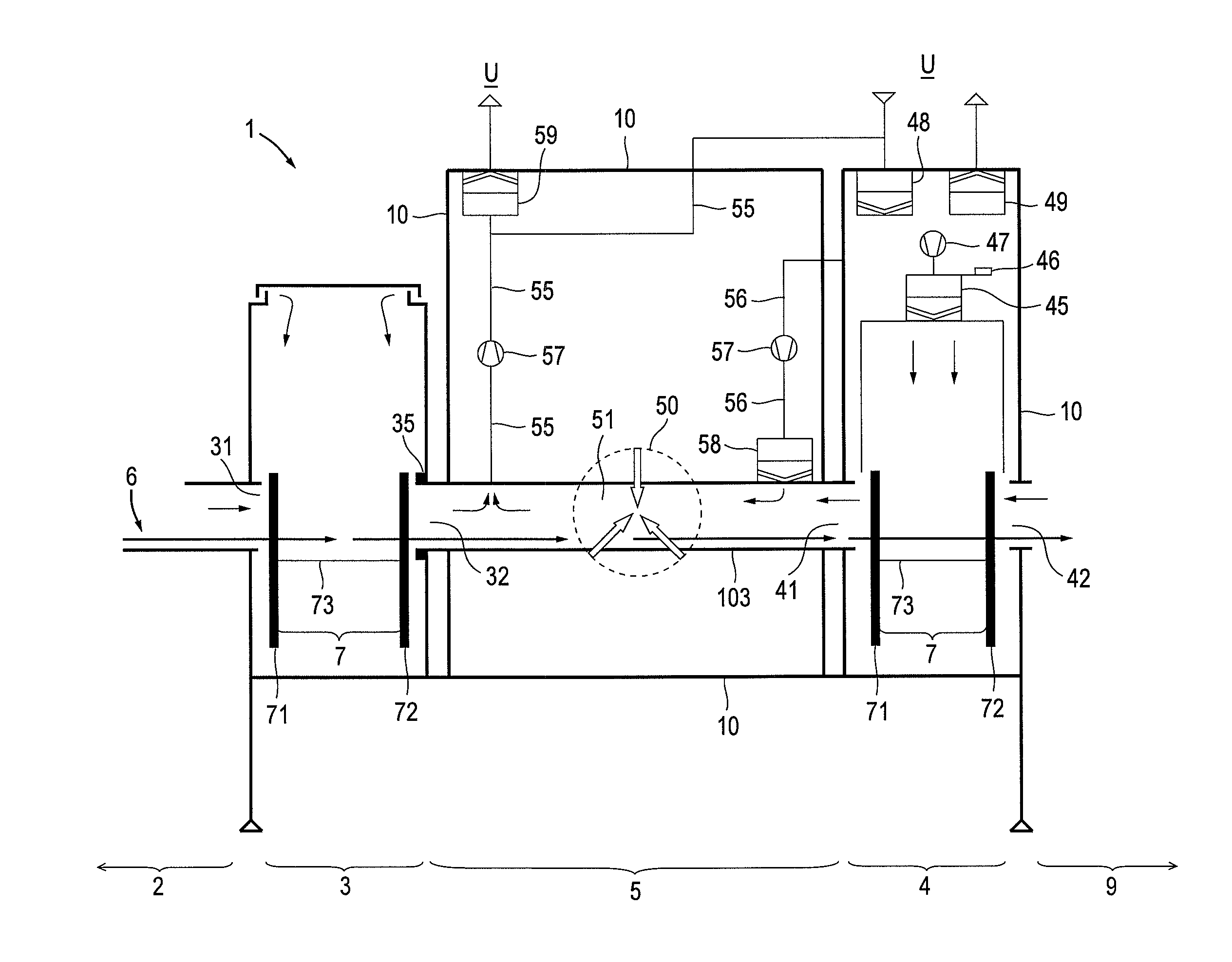
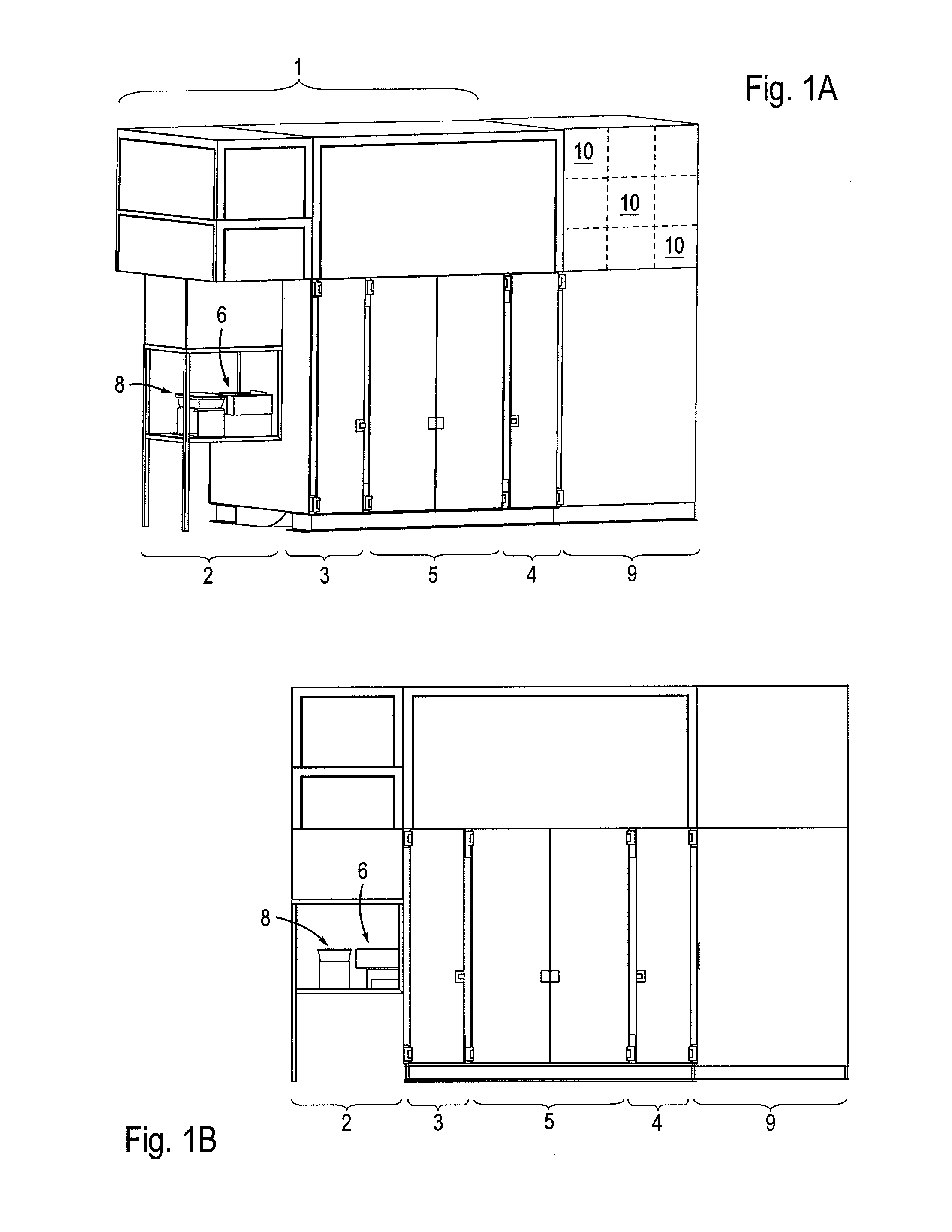
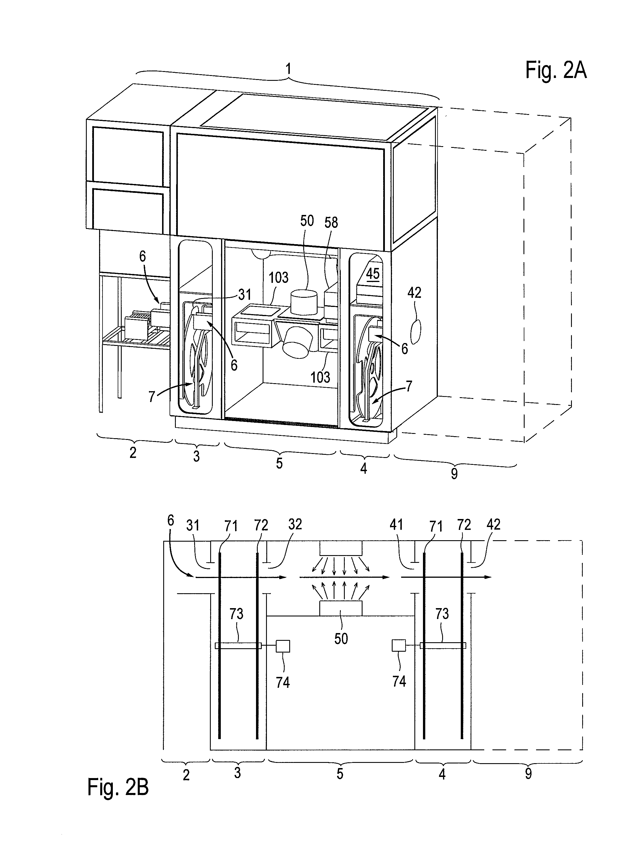
[0032]The detailed description of an exemplary embodiment of the installation for sterilizing objects by means of a radiation source follows below with reference to the appended drawings. Alternative solutions for the shield used in the installation are presented and, moreover, advantageous design details are disclosed in addition to the essential features.

[0033]The following provision applies for the entire description that follows: if reference numbers are contained in a figure for the purposes of unambiguity in the drawing but are not referred to in the directly associated text of the description, reference is made to their mentioning in preceding descriptions of figures. In the interest of clarity, the repeated labeling of components in subsequent figures is generally refrained from, as long as the drawing makes it clear without ambiguity that they are “recurring” components.

FIGS. 1A, 1B and 10

[0034]An irradiation zone 5 forms the center of the installation 1, said zone being pr...


PUM


Abstract

Disclosed is an installation (1) for sterilizing objects (8) by means of a radiation source (50). The installation (1) comprises an irradiation zone (5) in which the radiation source (50) is arranged. An entry zone (3), which is preceded by a feed zone (2), is mounted in front of the irradiation zone (5) while an exit zone (4), which is followed by a subsequent processing zone (9), is mounted behind the irradiation zone (5). A transportation line (6) that is used for conveying the objects (8) extends through the installation (1). One respective shield (7) is associated with the entry zone (3) and the exit zone (4). The entry zone (3) encompasses a first inlet opening (31) that has a passage to the feed zone (2) as well as a second inlet opening (32) which has a passage to the irradiation zone (5). The exit zone (4) has a first outlet (41) that has a passage to the irradiation zone (5) as well as a second outlet opening (42) which has a passage to the subsequent processing zone (9). The transportation line (6) extends in alignment through all inlet openings and outlet openings (31,32;41,42). The shields (7) are movable. In each position of the shields (7) in which the objects (8) that are conveyed through the installation (1) can penetrate one of the two inlet openings (31,32) or one of the two outlet openings (41,42), the other inlet opening (32,31) and the other outlet opening (42,41) are covered by the associated shield (7).

Description

FIELD OF THE INVENTION[0001]The present invention relates to an installation for sterilizing objects by means of a radiation source for generating X-ray, gamma or electron radiation, as is used, for example, in industry for the manufacture of medical single-use articles. Such an installation first of all has an irradiation zone, in which the radiation source is arranged. An entry zone is in front of the irradiation zone, and a feed zone for loading the installation with the objects to be treated is in front of said entry zone. An exit zone adjoins the irradiation zone and said exit zone is followed by a subsequent processing zone in which the irradiated objects are output for the subsequent manufacturing process which occurs here. The subsequent processing zone is typically furnished as an isolator or clean room, in which people can be active. Objects to be treated are, for example, containers with a multiplicity of initially empty injection syringes, in which the containers are to ...

Claims


Application Information

Patent Timeline
IPC IPC(8): A61L2/08
CPCA61L2/081A61L2/082G21K5/10A61L2202/11A61L2/08A61L2/087
Inventor NEUSCHWANDER, THOMASNEWMAN, JOHNSIGWARTH, VOLKERSMITH, PAUL ALEXANDER
Owner SKAN
Learn More