Illumination device

a technology of illumination device and led light, which is applied in the direction of electric variable regulation, process and machine control, instruments, etc., can solve the problems of light flicker, difficulty in cooperating with leds of transformer types, etc., and achieve the effect of reducing load, improving compatibility between leds, and reducing problems

Active Publication Date: 2012-07-05
KONINKLIJKE PHILIPS ELECTRONICS NV
View PDF9 Cites 21 Cited by
  • Summary
  • Abstract
  • Description
  • Claims
  • Application Information

AI Technical Summary

Benefits of technology

[0006]An object of the present invention is to overcome or at least reduce these problems.
[0007]Particularly, the present invention aims to improve the compatibility between LEDs and electronic transformers.
[0008]More particularly, the present invention aims to provide an illumination device incorporating one or more LEDs as light sources and capable of cooperating reliably with electronic transformers.
[0009]The present invention is based on the recognition that an electronic transformer requires a minimum load (minimum output current) in order to operate correctly, and that LEDs may be unable to provide such minimum load. Typically, the minimum load requirement of an electronic transformer is in the range of 20 W to 60 W, whereas LEDs typically provide a much lower load (which low power is actually seen as an important advantage of LEDs, and an important reason for using them to replace higher-power lamps in the first place).

Problems solved by technology

A problem is that this type of transformer has difficulty in cooperating with LEDs.
Typically, the transformer operation may be unstable, resulting in light flicker.

Method used


Image

  • Illumination device
  • Illumination device
  • Illumination device

Examples


Embodiment Construction

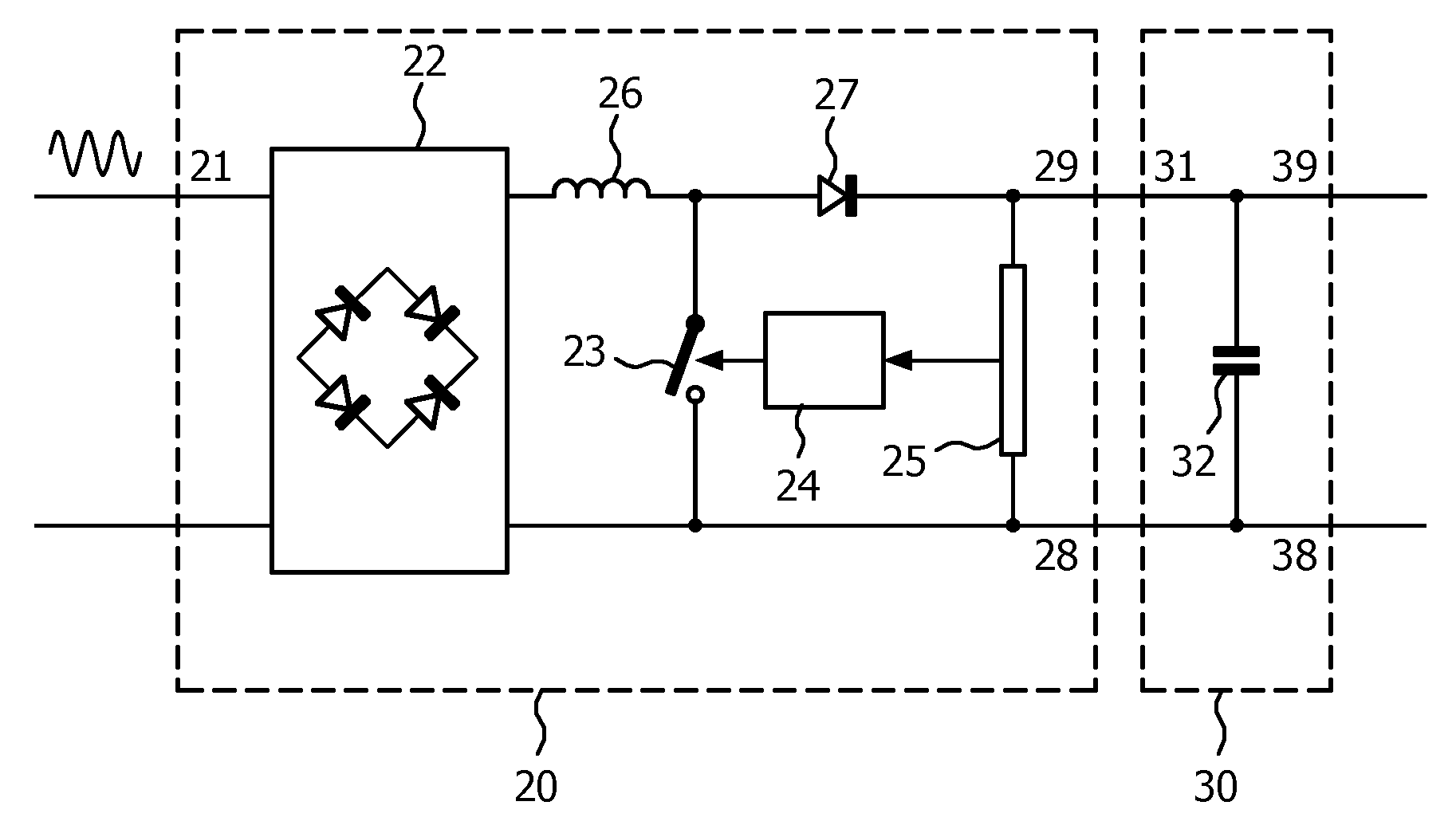
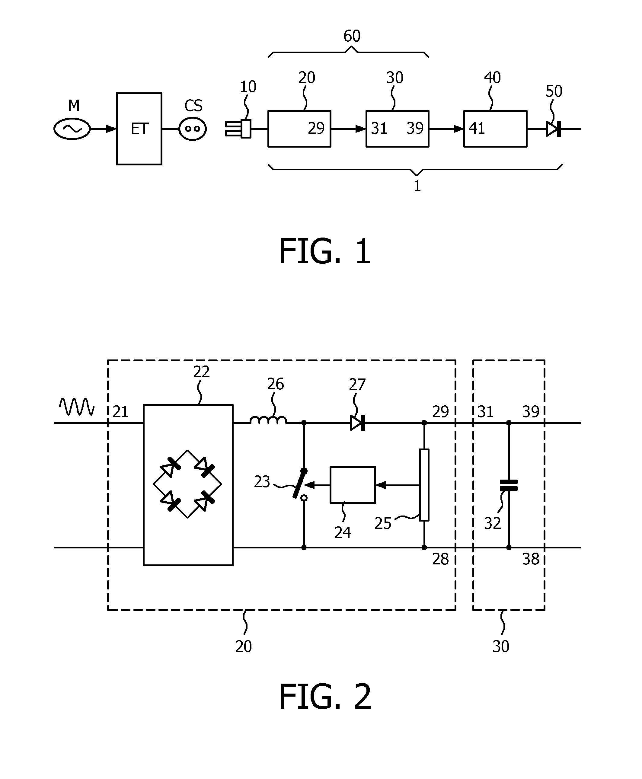
[0020]FIG. 1 schematically shows a block diagram of an illumination device 1 implemented in accordance with the present invention, connected to an electronic transformer ET which in turn is connected to mains M. The illumination device 1 has a three-stage design, comprising a power input stage 20, a power buffer stage 30, an LED driver stage 40 and finally one or more LEDs 50. As will be explained in more detail, the main task of the power input stage 20 is to keep the buffer 30 filled, taking into account the requirements of the supply, especially of the transformer ET, while the main task of the driver 40 is to drive the LED with power taken from the buffer, taking into account the requirements of the LED. Thus, even if such requirements may be mutually conflicting, they do not “collide” since they come into expression in different current circuits. In a steady state, the contents of the power buffer 30 is constant, on average. In one particular implementation, control is determin...


PUM


Abstract

An illumination device (1) comprises: at least one low-power light source (50); a power input stage (20) suitable for receiving AC low voltage from an electronic transformer (ET); a power buffer stage (30) having an input (31) connected to the input stage output (29); a driver (40) for driving the light source and receiving electric power supply from the power buffer stage. The power input stage generates output current pulses for charging the power buffer stage at a relatively low frequency, and during each output current pulse, the power input stage draws input current, the input current always having a current magnitude higher than a minimum load requirement of the electronic transformer.

Description

FIELD OF THE INVENTION[0001]The present invention relates in general to the field of lighting.BACKGROUND OF THE INVENTION[0002]In the field of lighting, many different types of light sources have been developed for illumination purposes. Depending on application, each type of light source may have specific advantages and disadvantages. In any case each type of light source has particular specifications, and power sources (or drivers) for such light sources have been developed for meeting the particular specifications.[0003]A recent development is the high-power LED as light source for illumination purposes. While of course drivers for illumination devices utilizing LEDs as light sources have been and are being developed, there is also a desire to utilize LEDs as replacement for the light sources in existing illumination devices (retrofit), in which case the electrical input signal to the lamp is generated by an existing driver adapted for meeting the particular specifications of the...

Claims


Application Information

Patent Timeline
Patent Type & Authority Applications(United States)
IPC IPC(8): H05B37/02H05B44/00
CPCH05B33/0842H02M3/155H05B45/00H05B45/38H05B45/3725H05B45/375H05B45/14Y02B20/30H05B45/37
Inventor EDDEANE, REDOUANETOUSAIN, ROBERTUS LEONARDUSHONTELE, BERTRAND JOHAN EDWARDCLAESSENS, DENNIS JOHANNES ANTONIUSEBERSON, ETIENNE NICOLAAS KATHALIJNTJE PAULUS MARIEJIANG, HONGVAEL, PHILIP LOUIS ZULMA
Owner KONINKLIJKE PHILIPS ELECTRONICS NV
Why Eureka
Try Eureka