
Antenna retaining device

a technology of retaining device and antenna, which is applied in the direction of antennas, antenna details, electrical devices, etc., can solve the problems of inability to adjust the orientation of radiating antenna, inability to steadily direct the radiating antenna at the retaining device,

Inactive Publication Date: 2012-07-05
HONG FU JIN PRECISION IND (SHENZHEN) CO LTD +1
View PDF5 Cites 12 Cited by
  • Summary
  • Abstract
  • Description
  • Claims
  • Application Information

AI Technical Summary

Problems solved by technology

However, the radiating antenna cannot be steadily directed at a retaining device and the orientation of the radiating antenna cannot be adjusted.

Method used


Image

  • Antenna retaining device
  • Antenna retaining device
  • Antenna retaining device

Examples


Embodiment Construction

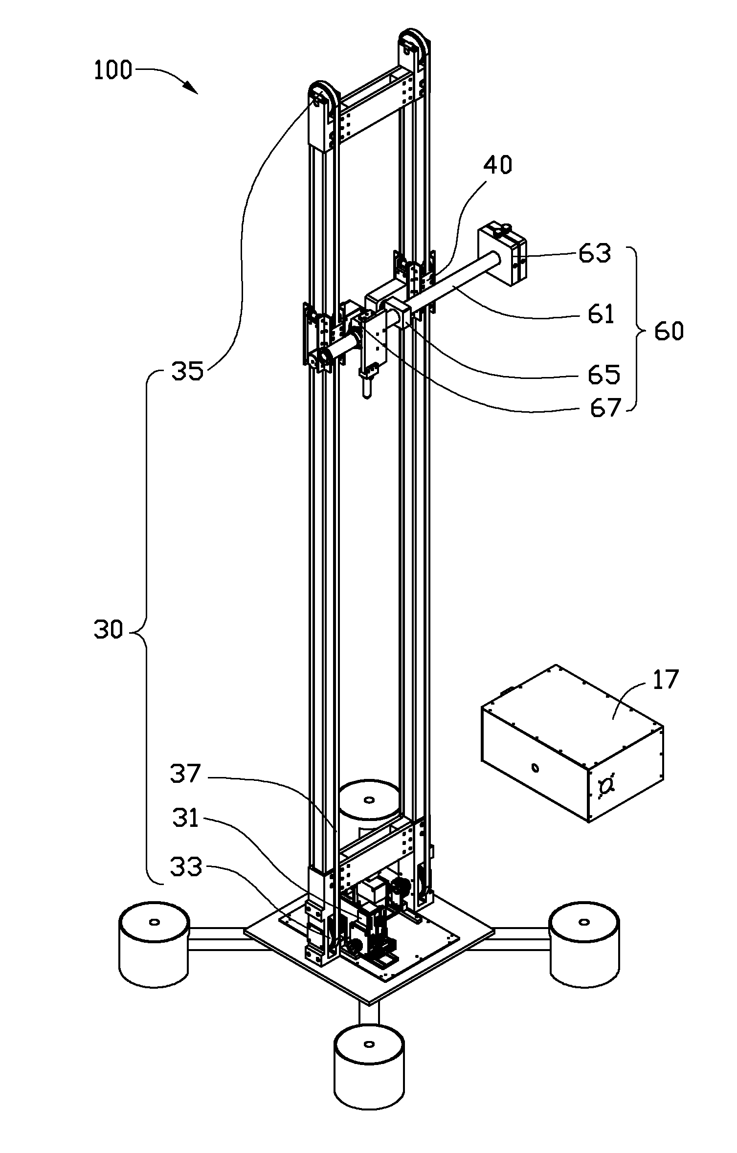
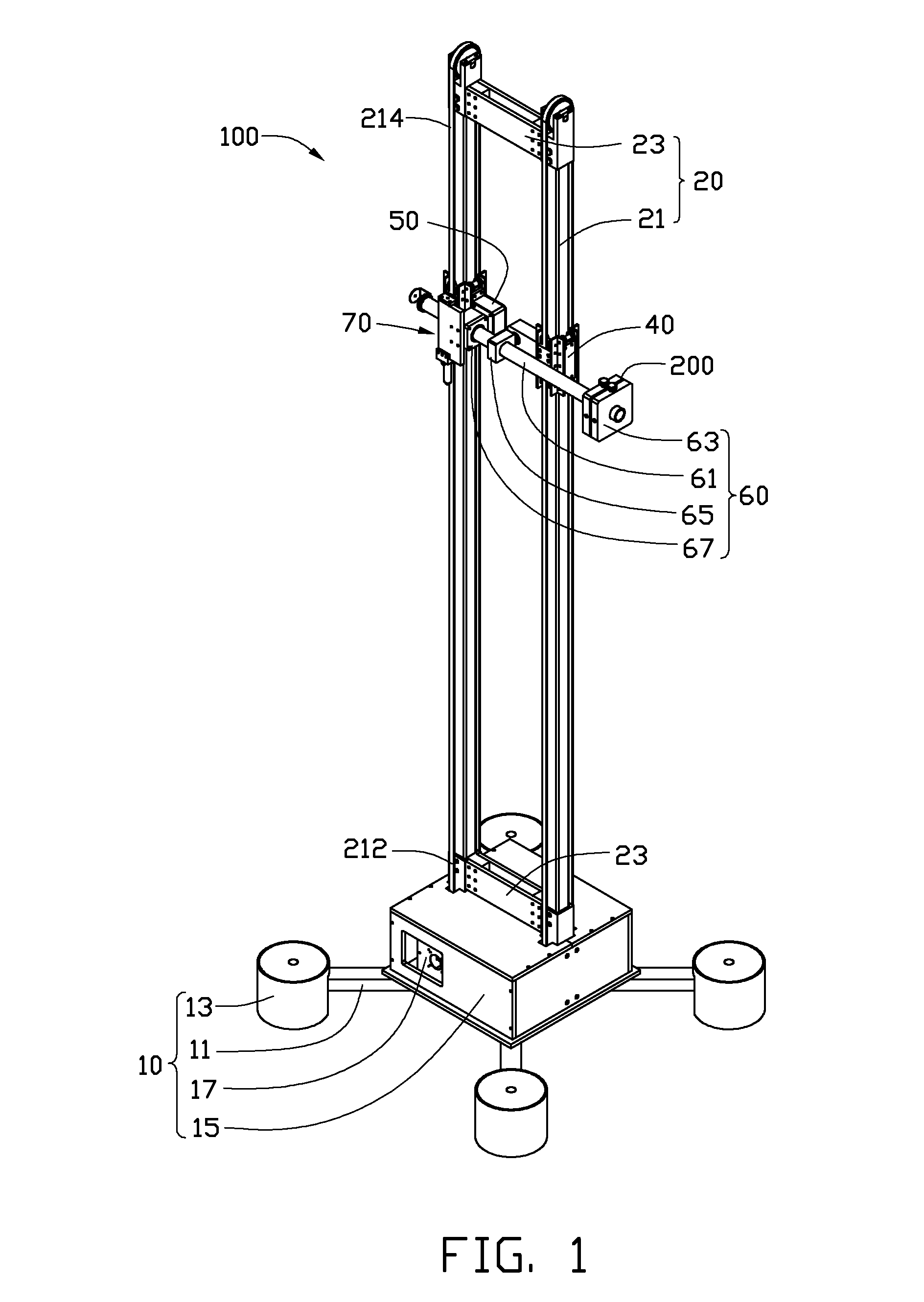
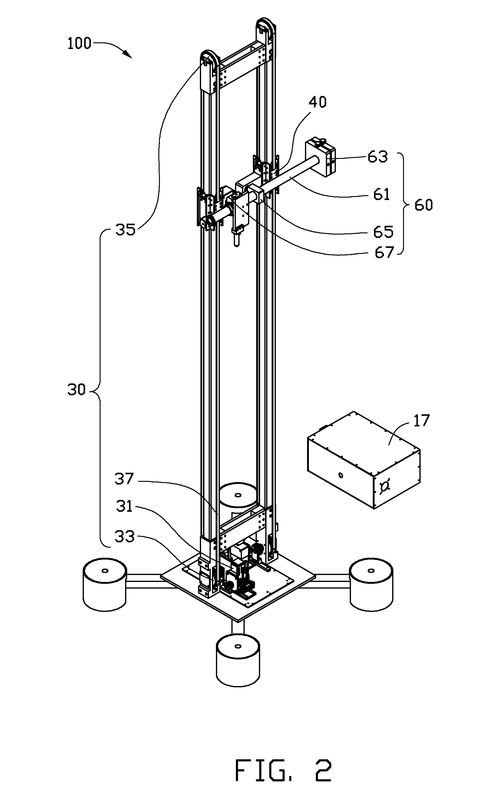
[0012]Referring to FIGS. 1-2, an exemplary embodiment of an antenna retaining device 100 retaining an antenna 200 used in testing the EMC of an electronic device is illustrated. The antenna retaining device 100 includes a base 10 and a support mechanism 20 mounted on the base 10. Two driving mechanisms 30 are mounted on the base 10. Two movable mechanisms 40 are movably mounted on the support mechanism 20. A loading board 50 is respectively mounted on each of the movable mechanisms 40. A retaining mechanism 60 is mounted on the loading boards 50. In addition, a rotation mechanism 70 is mounted on one of the loading boards 50. The antenna 200 is retained on the retaining mechanism 60. The driving mechanisms 30 drive the movable mechanisms 40 to move, causing the retaining mechanism 60 and the antenna 200 to move in unison.

[0013]The exemplary base 10 includes two crossing supporting rods 11, four pedestals 13, a mounting box 15 and a shielding can 17. Each pedestal 13 is mounted at on...


PUM


Abstract

An antenna retaining device includes two spaced upright beams, two movable mechanisms, each movable mechanism slidably mounts on one of the upright beams, a retaining mechanism includes two connecting elements a connecting rod connecting rod rotatably and movably mounted on the connecting elements. A retaining board is located on the connecting rod, the retaining board holds the antenna. The first connecting element is rotatably mounted on one of the movable mechanisms, the second connecting element is rotatably mounted on the other movable mechanism. Two driving mechanism, each driving one of the movable mechanisms to move along the their respective bar. When the motors drive the movable mechanisms to move at different speeds, the first connecting element and the second connecting element rotate relative to the their respective loading boards and move along the connecting rod, to adjust a direction of the connecting rod and retaining board.

Description

BACKGROUND[0001]1. Technical Field[0002]This disclosure relates to antenna retaining devices, particularly to antenna retaining devices for retaining an antenna used in testing electromagnetic compatibility (EMC) of an electronic device.[0003]2. Description of Related Art[0004]EMC is the branch of electrical sciences which studies the unintentional generation, propagation and reception of electromagnetic energy with reference to the unwanted effects (Electromagnetic interference, or EMI) that such energy may induce. To test EMC of a particular device typically involves a high-powered source of RF or EM pulse energy and a radiating antenna to direct the energy at the device under test. The radiating antenna is typically located in a movable retaining device, to change the distance between the radiating antenna and the particular device. However, the radiating antenna cannot be steadily directed at a retaining device and the orientation of the radiating antenna cannot be adjusted.[000...

Claims


Application Information

Patent Timeline
IPC IPC(8): H01Q3/02
CPCG01R31/002H01Q3/08H01Q1/1235
Inventor HUANG, TENG-TSUNGHU, YONG-BINGYAN, ZHANG-SHENGCHENG, GONG-SHUISHANG, ZHAN
Owner HONG FU JIN PRECISION IND (SHENZHEN) CO LTD
Learn More