Capacitive touch screen

a capacitive touch and touch screen technology, applied in the field of capacitive touch screens, can solve the problems of reducing the signal or signal, severely distorting the variations of capacitive coupling of a true touch, and misjudgment of the true touch, so as to facilitate the flow of signals out, facilitate the flow of signals, and improve the tolerance to untrue touch effects

Active Publication Date: 2012-07-05
EGALAX EMPIA TECH INC
View PDF8 Cites 51 Cited by
  • Summary
  • Abstract
  • Description
  • Claims
  • Application Information

AI Technical Summary

Benefits of technology

[0015]When mutual capacitive multi-touch detection is performed on a mutual-capacitive multi-touch screen, the driving signal may flow from a first finger to a second finger of the same palm by capacitive coupling, which may reduce the signal or signal variation indicating the location of a true touch, causing misjudgment of the true touch. One objective of the present invention is thus to reduce the negative-touch effect flowing between the fingers.

Problems solved by technology

When mutual capacitive multi-touch detection is performed on a mutual-capacitive multi-touch screen, the driving signal may flow from a first finger to a second finger of the same palm by capacitive coupling, which may reduce the signal or signal variation indicating the location of a true touch, causing misjudgment of the true touch.
When mutual capacitive multi-touch detection is performed on a mutual-capacitive multi-touch screen, capacitive coupling of signals flowing between multiple external conductive objects and into the multi-touch screen may severely distort the variations in detected capacitive coupling of a true touch.
In order to avoid this problem, the thickness of an insulating surface layer cannot effectively be made thinner.

Method used


Image

  • Capacitive touch screen
  • Capacitive touch screen
  • Capacitive touch screen

Examples


first embodiment

[0105]Referring to FIG. 3A, a capacitive touch screen according to the present invention is provided. It includes a conductive strip pattern 30, which includes a plurality of first conductive strips 31 and a plurality of second conductive strips 32. The first conductive strips 31 are formed by a plurality of first conductive pads 33 connected together. The second conductive strips 32 are formed by a plurality of second conductive pads 34 connected together. The second conductive pads have a plurality of openings 35.

[0106]Each second conductive pad may have one or more openings. The size (or area) of the opening allows the area of the first conductive strip covered by a touch range of a valid touch larger than a predetermined condition to be greater than the area of the second conductive strip covered. The valid touch may mean that when an external conductive object touches the conductive strip pattern, its location can be determined correctly. With different physical properties of t...

second embodiment

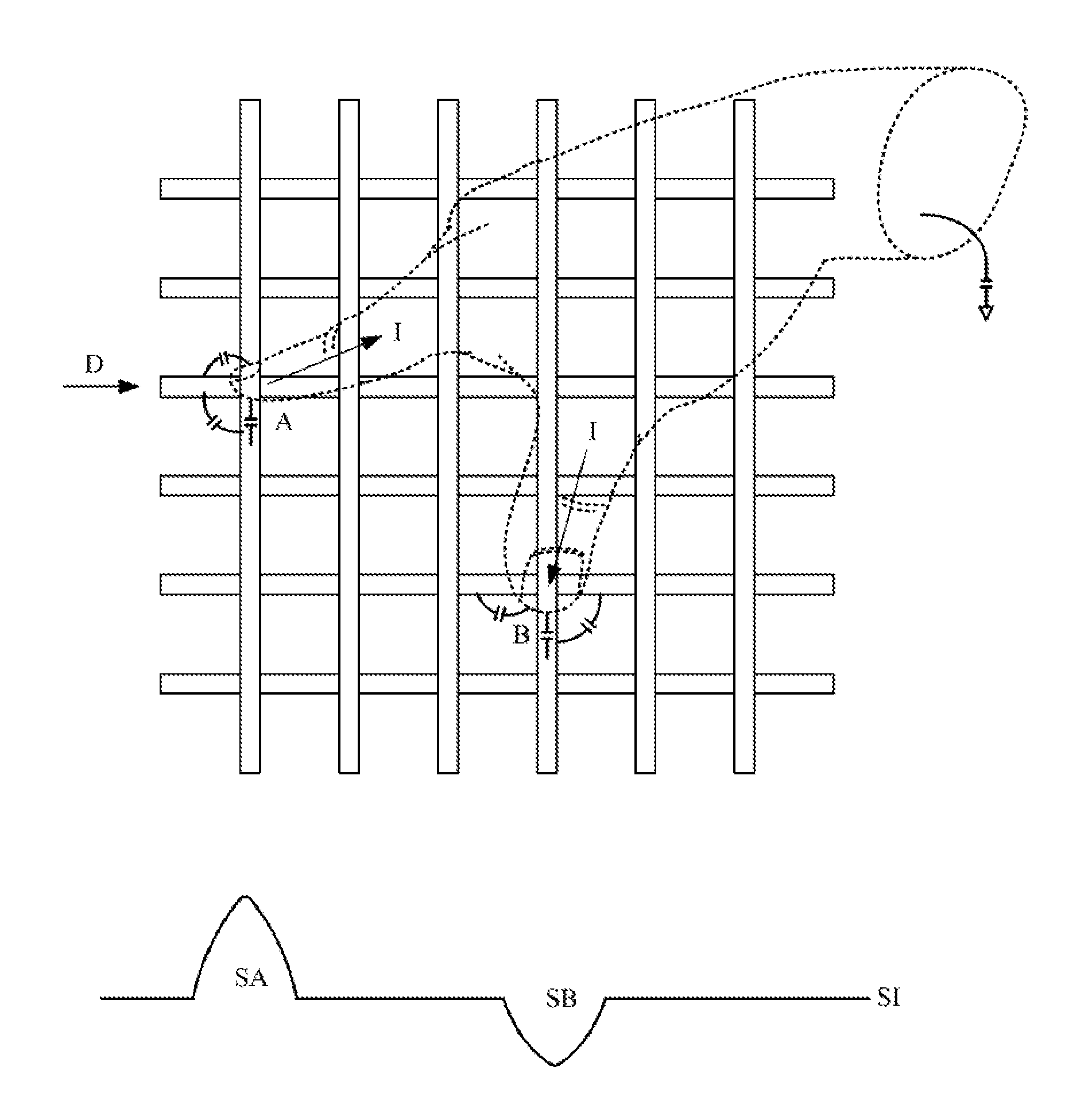
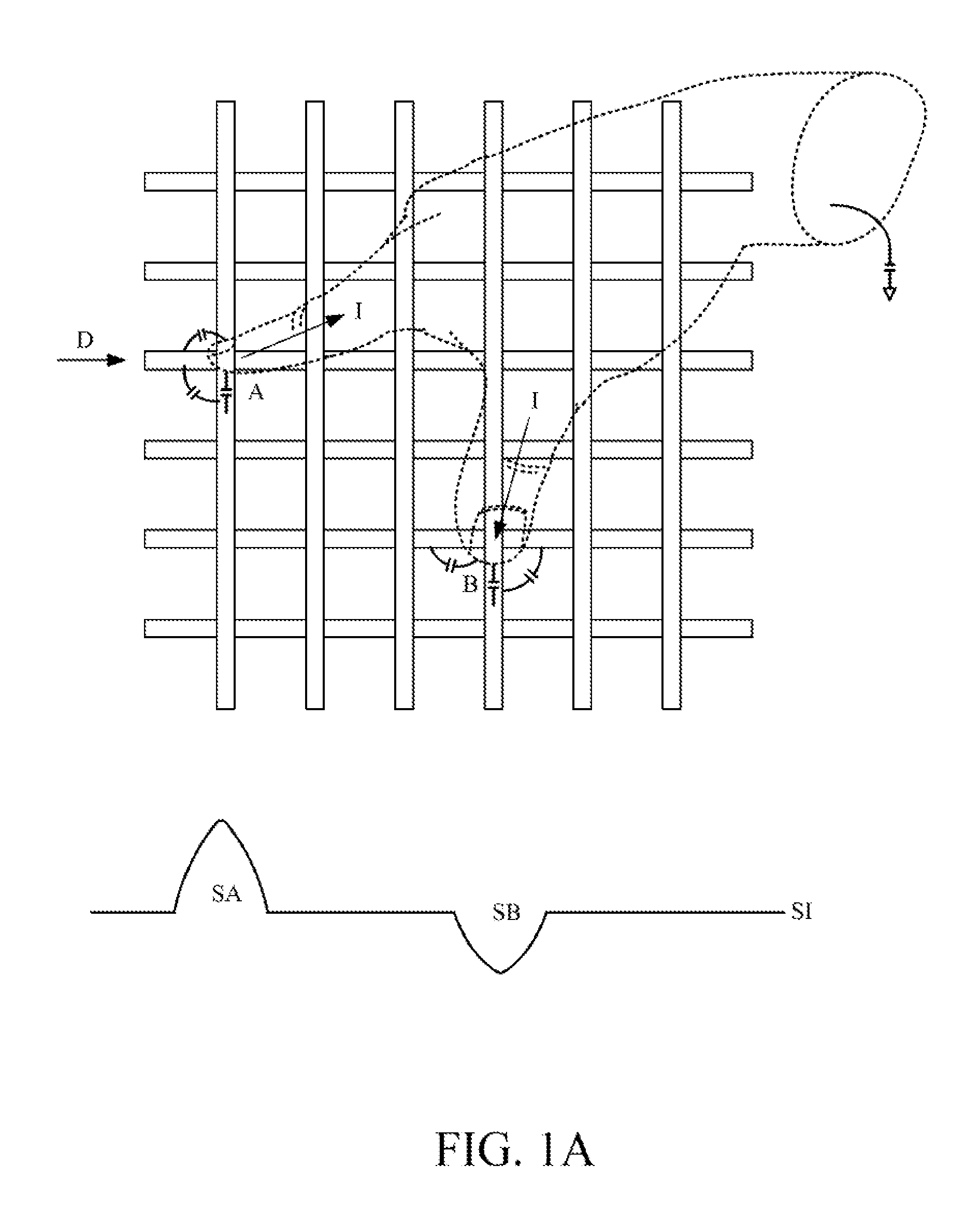
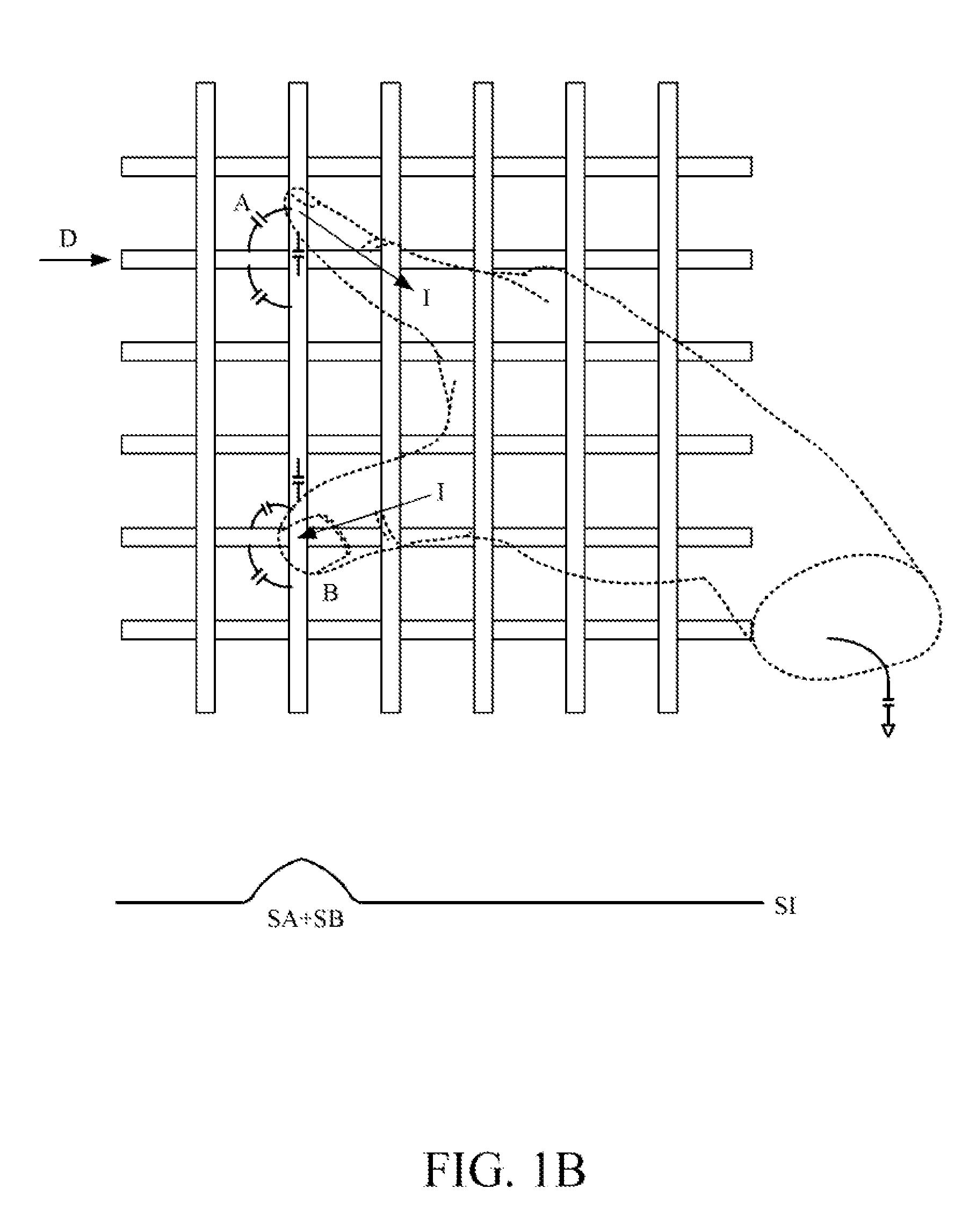
[0124]Referring to FIG. 5, a flowchart illustrating a detection method for a capacitive touch screen according to the present invention is shown. First, in step 510, a capacitive touch sensitive display without a rear shielding layer is provided, which includes a plurality of exposed conductive strips and a display. The conductive strips include a plurality of first conductive strips operatively provided with a driving signal during mutual capacitive detection and a plurality of second conductive strips providing mutual capacitive coupling signals. The conductive strips are separated from each other. In addition, there is no rear shielding layer provided with a DC signal between the display and the conductive strips. The conductive strip pattern allows that, when a touch range of each external conductive object on the capacitive touch screen is larger than a predetermined condition, capacitive coupling between each external conductive object and the first conductive strip is greater...

fifth embodiment

[0139]Referring to FIG. 7C, a schematic diagram depicting a guarding pattern according to the present invention is shown. A third conductive strip 73 is provided at either side of a first conductive strip 31, and a fourth conductive strip 74 is provided at either side of a second conductive strip 32, wherein the third conductive strips 73 and the fourth conductive strips 74 form the guarding pattern. In other words, the first conductive strips 31 and the second conductive strips 32 intersect each other at a plurality of intersecting regions, and a guarding conductive strip (i.e. a third conductive strip 73 and a fourth conductive strip 74) is provided at either side of each of the first conductive strips 31 and second conductive strips 32. Moreover, the first conductive strips 31, the second conductive strips 32, the third conductive strips 73 and the fourth conductive strip 74 are isolated from one another, wherein the first conductive strips 31 and the third conductive strips 73 o...


PUM


Abstract

The present invention provides a mutual capacitive multi-touch screen, which includes a guarding pattern and a conductive strip pattern exposed from each other. The conductive strip pattern includes a plurality of first conductive strips provided with a driving signal and a plurality of second conductive strips for providing mutual capacitive coupling signals, and the guarding pattern is provided with a DC signal. The guarding pattern allows that, when a touch range of each external conductive object is larger than a predetermined condition, capacitive coupling between each external conductive object and the guarding pattern or capacitive coupling between each external conductive object and the first conductive strips and the guarding pattern is greater than capacitive coupling between each external conductive object and the second conductive strips.

Description

CROSS REFERENCE TO RELATED APPLICATIONS[0001]This application claims the benefits of U.S. Provisional Application No. 61 / 472,971, filed on Apr. 7, 2011, Provisional Application No. 61 / 435,568, filed on Jan. 24, 2011 and U.S. Provisional Application No. 61 / 428,499, filed on Dec. 30, 2010, which are herein incorporated by reference for all intents and purposes.BACKGROUND OF THE INVENTION[0002]1. Field of the Invention[0003]The present invention relates to capacitive touch screens, and more particularly, to a capacitive touch screen that reduces the effect of negative touches.[0004]2. Description of the Prior Art[0005]Referring to FIG. 1A, when a driving signal D is provided by a conductive strip being driven, the signal may flow from a first finger A to another finger B of the same hand, such that, during scanning of sensing information SI, sensed conductive strips corresponding to fingers A and B will sense variations in mutual-capacitive coupling signals, such as touch-related sensi...

Claims


Application Information

Patent Timeline
IPC IPC(8): G06F3/044
CPCG06F3/0418G06F3/044G06F2203/04104G06F2203/04103G06F2203/04111G06F3/0416G06F2203/04107G06F3/0412G06F2203/041G06F3/04166G06F3/0445G06F3/0446G06F3/0447
Inventor CHANG, CHIN-FU
Owner EGALAX EMPIA TECH INC
Why Eureka
Try Eureka