Lighting device

a technology of light source and support device, which is applied in the direction of lighting and heating apparatus, point-like light source, lighting support device, etc., can solve the problem of hardly any air flow, and achieve the effect of reducing the difficulty of air flow

Active Publication Date: 2012-07-05
KONINKLIJKE PHILIPS ELECTRONICS NV
View PDF4 Cites 10 Cited by
  • Summary
  • Abstract
  • Description
  • Claims
  • Application Information

AI Technical Summary

Benefits of technology

[0016]By integrating the air inlet aperture and air outlet ap...

Problems solved by technology

If such a lighting device is mounted in a ceiling or a luminaire which is cl...

Method used


Image

  • Lighting device
  • Lighting device
  • Lighting device

Examples


first embodiment

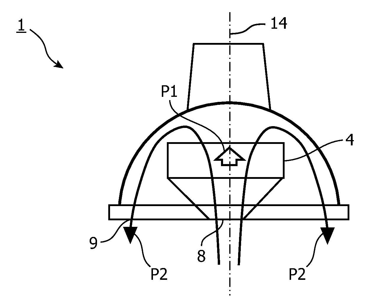
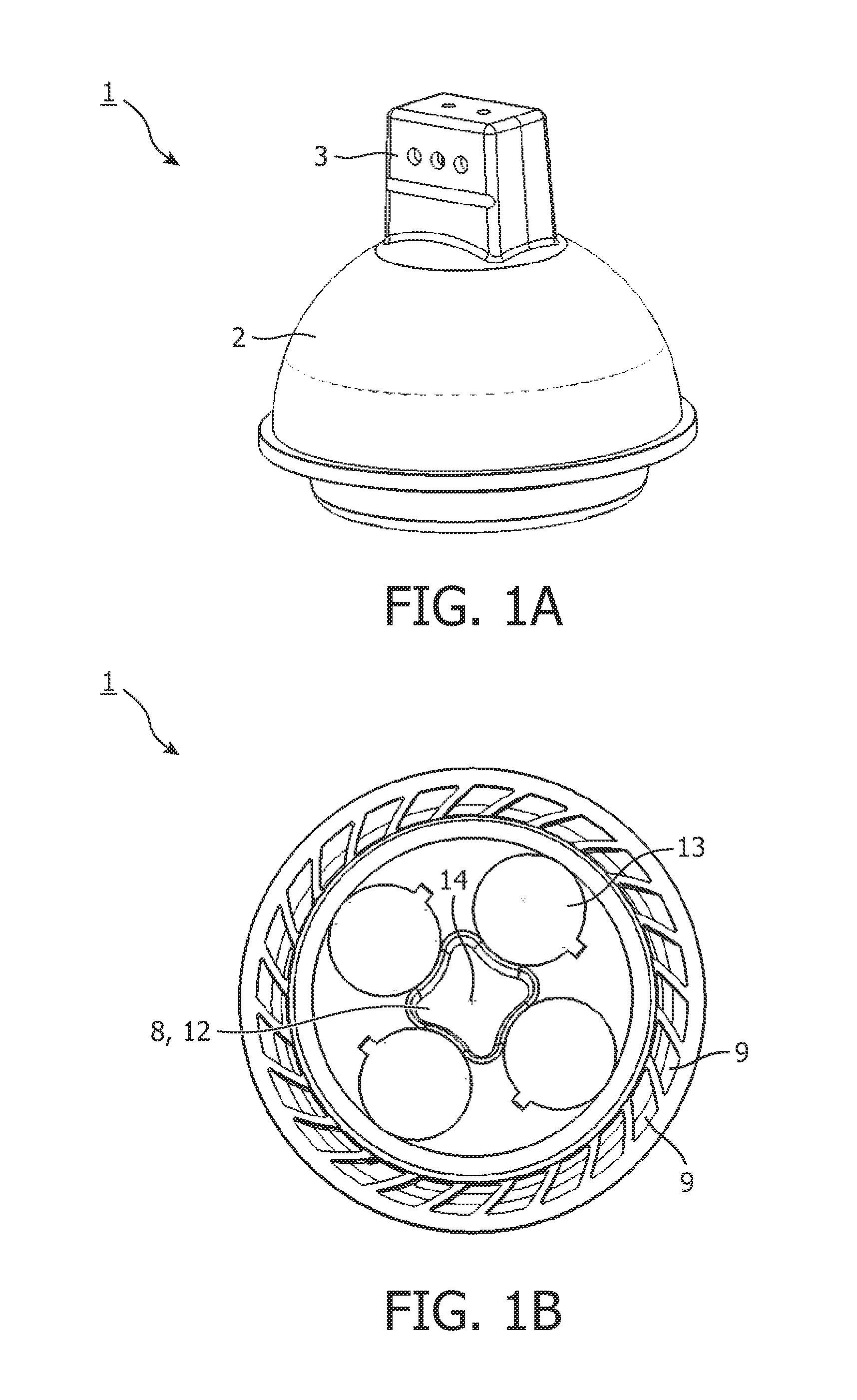
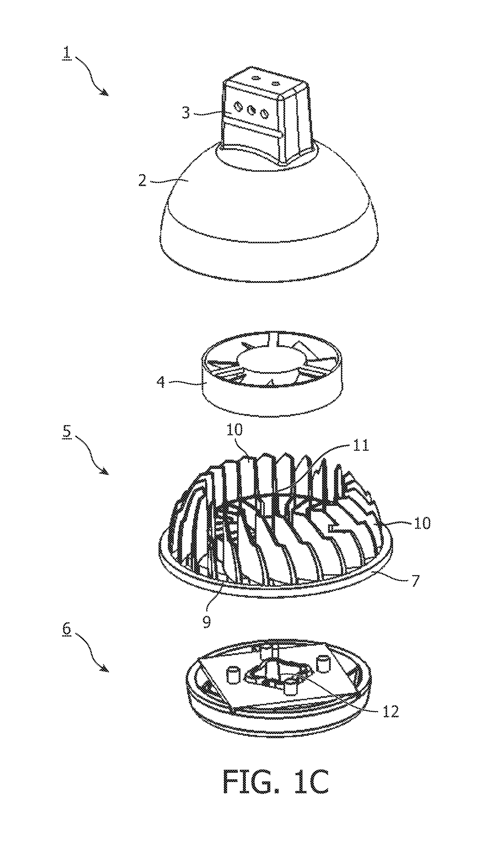
[0024]FIGS. 1A-1C show a lighting device 1 according to the invention. The lighting device 1 comprises a cup-shaped housing 2, a socket 3 connected to the housing 2, a ventilator unit 4, a heat sink 5 and a lighting unit 6.

[0025]The heat sink 5 comprises a base plate 7 provided with a centrally located aperture 8 and a number of apertures 9 located around the aperture 8 at a distance therefrom. The heat sink 5 also comprises a number of fins 10 attached to the base plate 7 and situated between the apertures 9. Between the fins 10 a cavity 11 is available in which the ventilator unit 4 is positioned. The ventilator unit 4 is located parallel to the base plate 7.

[0026]The lighting unit 6 comprises a centrally located aperture 12 and four LEDs 13 located in a circle around the centrally located aperture 12. The LEDs 13 are electrically coupled to the socket 3. The light emitting surfaces of the LEDs 13 are located on the same side of the lighting device 1 as the apertures 8, 9, 12; in ...

second embodiment

[0030]FIGS. 4A-4C and 5 show a lighting device 21 according to the invention. The lighting device 21 comprises a cup-shaped housing 22, a socket 23 connected to the housing 22, a ventilator unit 24, a heat sink 25 and a lighting unit 26.

[0031]The heat sink 25 comprises a base plate 27 provided with a number of apertures 28 located around a central axis 29 of the lighting device 21. The heat sink 25 also comprises a number of fins 30 attached to the base plate 27 and situated between the apertures 28. Between the fins 30 a cavity 31 is available in which the ventilator unit 24 is positioned. The ventilator unit 24 is located perpendicularly to the base plate 27.

[0032]The lighting unit 26 comprises four LEDs 33 located in a circle around the central axis 29. The LEDs 33 are electrically coupled to the socket 23. The lighting device 26 comprises inclined walls 34 forming air guiding means for guiding air towards the apertures 28 near the air entrance side of the ventilator unit 24 and ...


PUM


Abstract

A lighting device comprises at least a light source (13, 33), a light emitting surface, an air inlet aperture (8, 9, 28), an air outlet aperture (8, 9, 28) and a cooling unit (4, 24) for moving air from the air inlet aperture (8, 9, 28) through the cooling unit (4, 24) to the air outlet. The air inlet aperture (8, 9, 28) and the air outlet aperture (8, 9, 28) are both located on the same side of the lighting device as at least part of the light emitting surface.

Description

FIELD OF THE INVENTION[0001]The invention relates to a lighting device comprising at least a light source, a light emitting surface, an air inlet aperture, an air outlet aperture and a cooling unit for moving air from the air inlet aperture through the cooling unit to the air outlet aperture.BACKGROUND OF THE INVENTION[0002]Such a lighting device, which is known from US 2005 / 0111234 A1, comprises a surface from which light is emitted to illuminate a room, for example. The light emitting surface of the lighting device is located at a front side of the lighting device. The lighting device comprises a shell and an optical reflector. A space between the shell and the optical reflector serves as an air channel. An air inlet aperture of the air channel is located near a socket of the lighting device whilst an air outlet aperture of the air channel is located at the front side of the lighting device. A ventilator unit is located between the air inlet aperture and the air outlet aperture fo...

Claims


Application Information

Patent Timeline
IPC IPC(8): F21S4/00
CPCF21Y2101/02F21Y2105/001F21V29/673F21V29/77F21V29/75F21V29/76F21V29/677F21Y2105/10F21Y2115/10F21V29/83F21V29/74
Inventor KEMPS, PETER ADRIANUS ALBERTTOUSAIN, ROBERTUS LEONARDUSBENOY, DANIEL ANTONTREURNIET, THEODOOR CORNELISUITBEIJERSE, BASTIAANDEN DULK, JACOB CORNELIS PAUL
Owner KONINKLIJKE PHILIPS ELECTRONICS NV
Why Eureka
Try Eureka