Nitrogen and oxygen separation using vacuum swing adsorption
a vacuum swing and adsorption technology, applied in the vacuum field, can solve the problems of unsatisfactory liquefaction, difficulty, and significant power and potentially elaborate machinery for effective gas separation, and achieve the effects of durable and reliable gas separation, low cost, and less power
- Summary
- Abstract
- Description
- Claims
- Application Information
AI Technical Summary
Benefits of technology
Problems solved by technology
Method used
Image
Examples
first embodiment
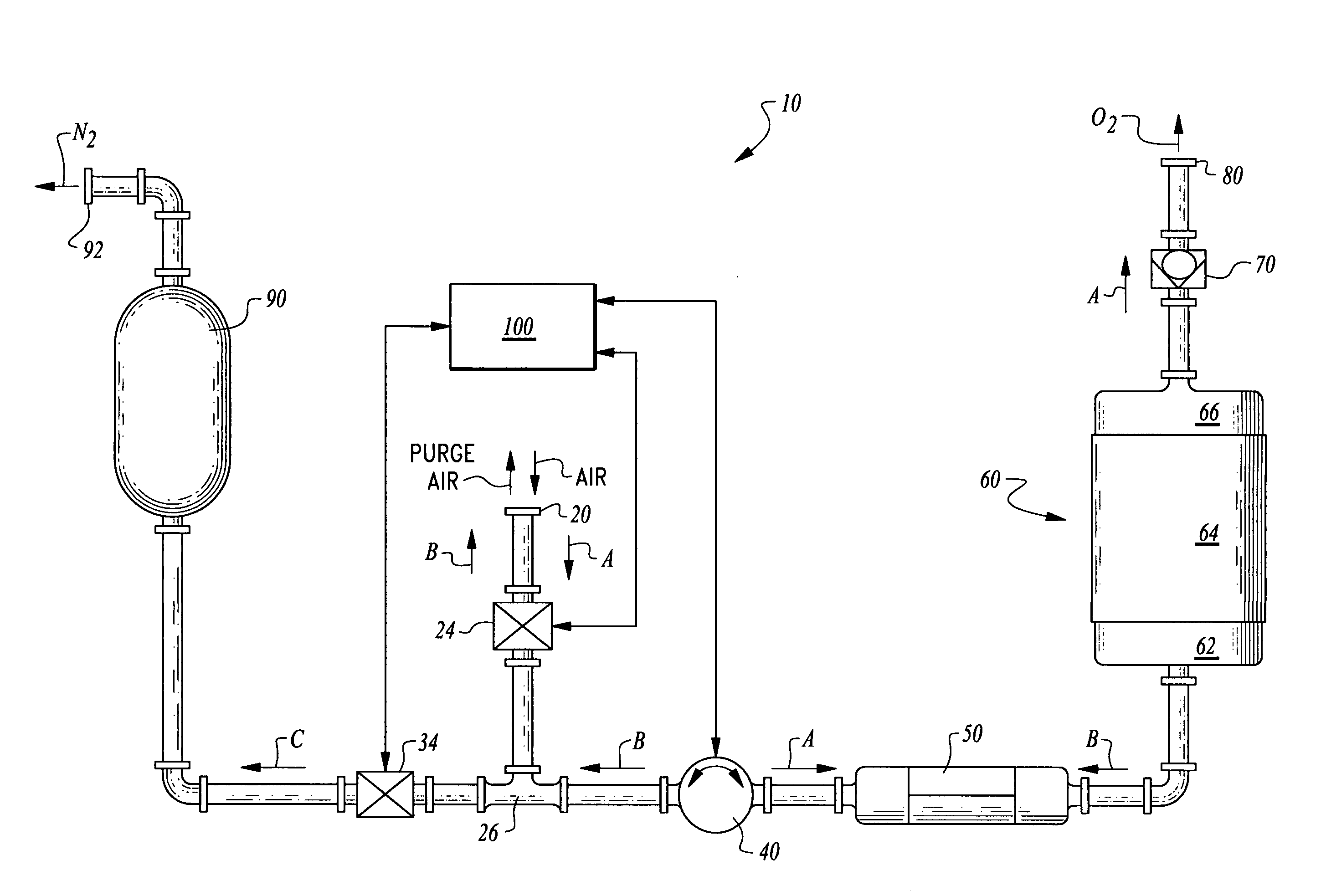
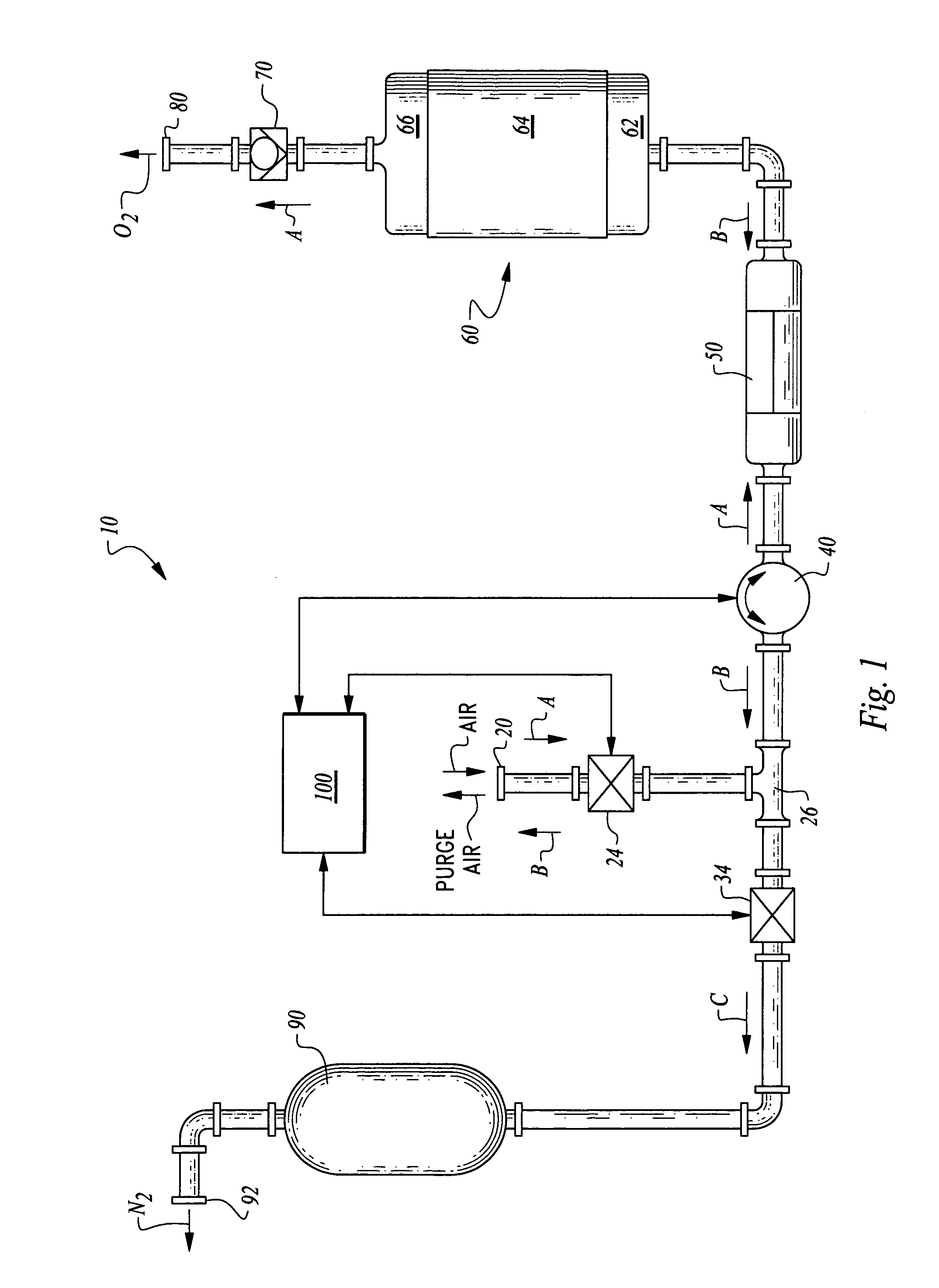
[0033]In essence, and with particular reference to FIG. 1, basic details of this invention are illustrated in the context of this The system 10 includes the inlet 20 for air to enter the system 10. The inlet 20 is coupled to a blower or other gas compression element. At least one valve is interposed between the inlet 20 and the blower 40. In this embodiment an inlet valve 24 and feed valve 34 are located on an inlet 20 side of the blower 40. A heat exchanger 50 is optionally provided on a side of the blower 40 opposite the inlet 20.
[0034]A chamber 60 is also provided on a side of the blower 40 opposite the inlet 20. This chamber 60 is configured to support media which selectively adsorbs nitrogen. A check valve 70 or other valve is provided on a side of the chamber 60 opposite the blower 40 and adjacent an exhaust 80. A buffer tank 90 is provided downstream of the feed valve 34 for collection of nitrogen therein, typically as part of a nitrogen supply system.
second embodiment
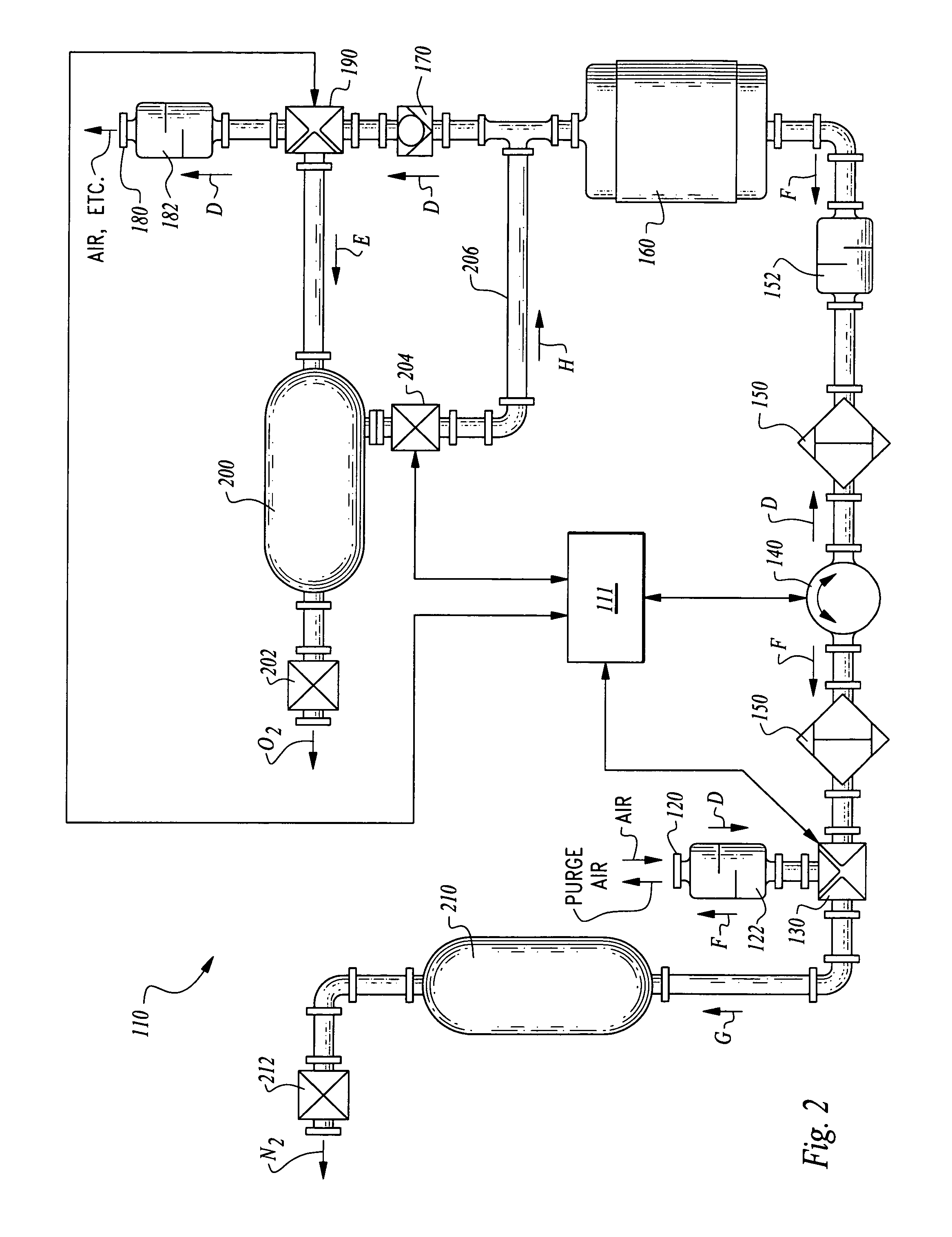
[0035]In a second embodiment shown in FIG. 2, the nitrogen and oxygen separation system 110 is supplied with analogous elements to those of the system 10 of FIG. 1. In particular, an inlet 120 is provided upstream of a blower 140 with at least one valve (in this embodiment provided as an inlet three-way valve 130) interposed between the inlet 120 and the blower 140. Heat exchangers 150 are optionally provided on either side of the blower 140. The chamber 160 is provided on a side of the blower 140 opposite the inlet 120. A check valve 170 is provided on a side of the chamber 160 opposite the blower 140. An exhaust three-way valve 190 is located downstream of the check valve 170 which leads to both an exhaust 180 and an oxygen buffer tank 200. With this nitrogen and oxygen separation system 110, oxygen and nitrogen are simultaneously separated from each other and collected in the oxygen buffer tank 200 or the nitrogen buffer tank 210.
[0036]More specifically, and with reference to FIG...
PUM
| Property | Measurement | Unit |
|---|---|---|
| Pressure | aaaaa | aaaaa |
| Flow rate | aaaaa | aaaaa |
Abstract
Description
Claims
Application Information
 - R&D
- Intellectual Property
- Life Sciences
- Materials
- Tech Scout
- Unparalleled Data Quality
- Higher Quality Content
- 60% Fewer Hallucinations
Browse by: Latest US Patents, China's latest patents, Technical Efficacy Thesaurus, Application Domain, Technology Topic, Popular Technical Reports.
© 2025 PatSnap. All rights reserved.Legal|Privacy policy|Modern Slavery Act Transparency Statement|Sitemap|About US| Contact US: help@patsnap.com


