Inflatable diving safety marker

a safety marker and inflatable technology, applied in underwater equipment, waterborne vessel navigational aids, special-purpose vessels, etc., can solve the problems of unnecessary weight, device adding unnecessary weight to diver's equipment, and not being able to be easily released

Inactive Publication Date: 2012-07-05
PISOR DONALD
View PDF3 Cites 5 Cited by
  • Summary
  • Abstract
  • Description
  • Claims
  • Application Information

AI Technical Summary

Benefits of technology

[0018]In another embodiment the bladder of the inflatable safety marker has a reflective surface able to reflect light or a radio frequency signal. The light reflected may be visible of infrared light.
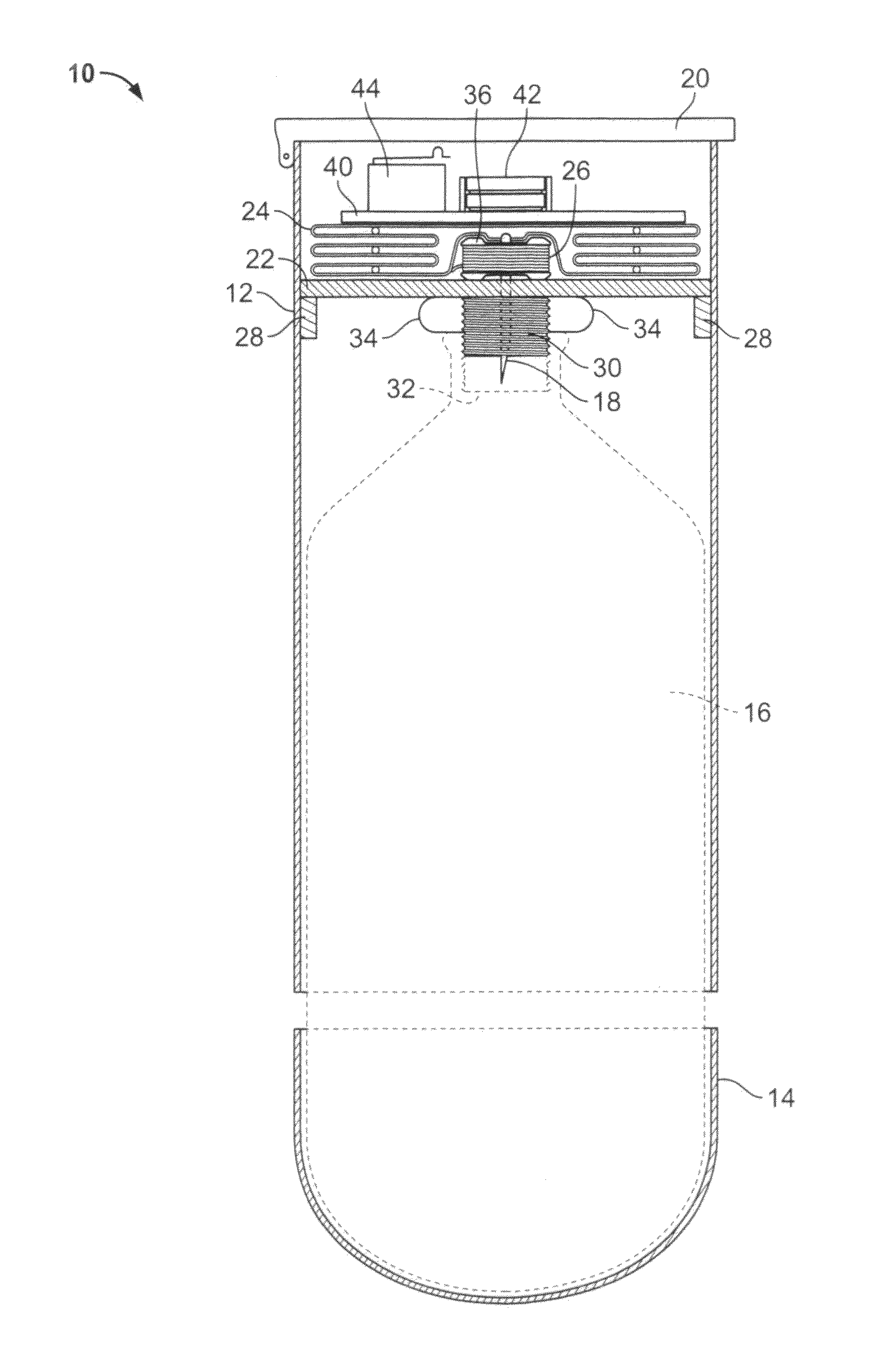
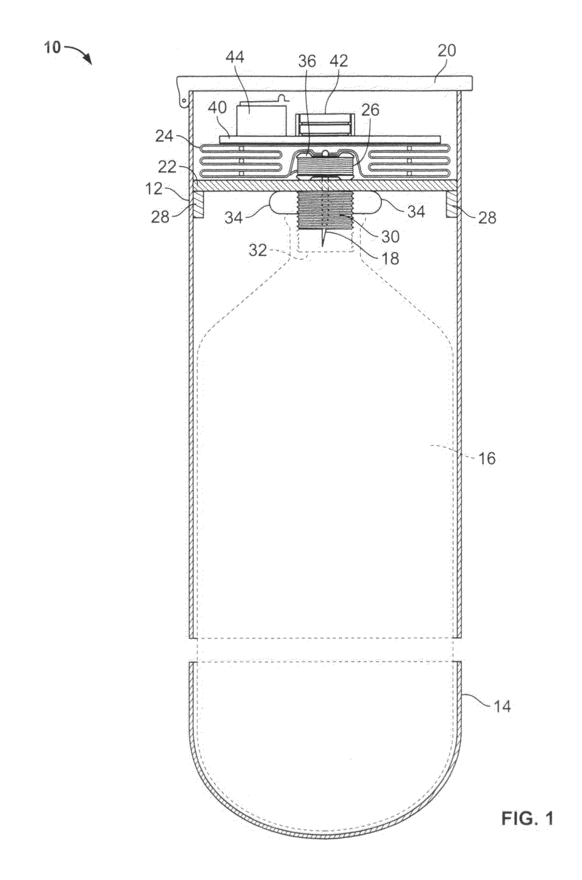
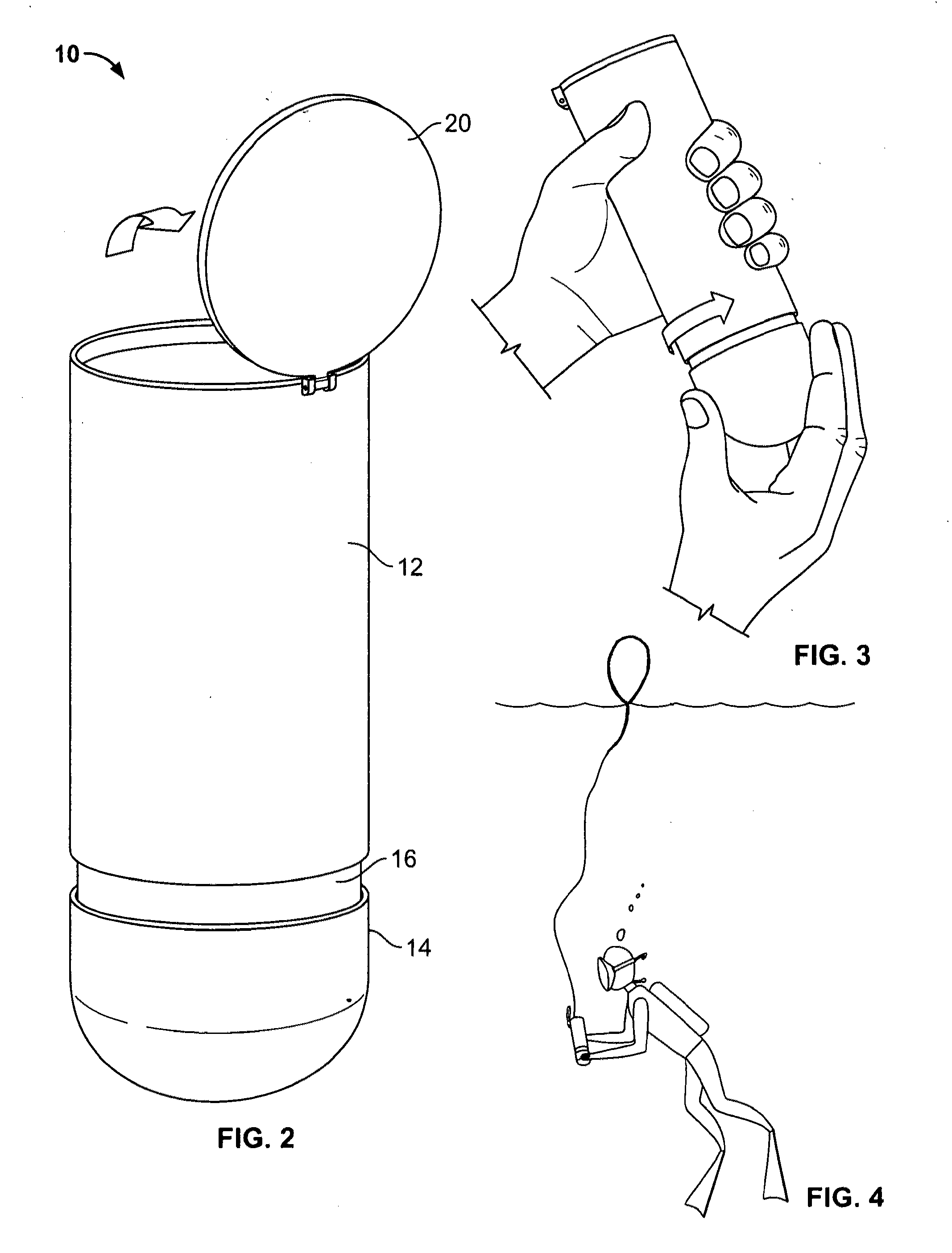
[0019]Another aspect of the present invention is a method of deploying the inflatable safety marker. The method comprises the steps of twisting the gas canister, or lower portion of the housing affixed to the base of the canister, in a clockwise direction with respect to the housing or upper portion of

Problems solved by technology

A variety of markers designed to indicate the location of a submerged diver have been provided, however none addresses the needs of a diver in distress.
Unfortunately, the marker requires that the diver manually inflate the buoy through the valve means, which may not be possible if a diver is in distress.
In addition, such a device adds unnecessary weight to a diver's equipment that may not be easily released in an emergency for an immediate ascent.
Like U.S. Pat. No. 5,141,458, this device also requires manual inflation and the reel adds unnecessary weight to the diver's equipment.
The disadvantage of this device is that because it does not have an inflatable floatation element it is not compact.
Its size is cumbersome and adds an additional element to the d

Method used


Image

  • Inflatable diving safety marker
  • Inflatable diving safety marker
  • Inflatable diving safety marker

Examples


Embodiment Construction

[0024]Unless defined otherwise, all terms used herein have the same meaning as are commonly understood by one of skill in the art to which this invention belongs. All patents, patent applications and publications referred to throughout the disclosure herein are incorporated by reference in their entirety. In the event that there is a plurality of definitions for a term herein, those in this section prevail.

[0025]The term “affixable” as used herein in reference to the interaction between the gas canister and the cylindrical hollow housing is any method of securing the gas canister in the housing that allows ease of use. For example, providing a threaded perimeter on the depending threaded cylindrical skirt on the lower surface of the puncture plate. This would allow the gas canister to be positioned adjacent to the sharp end of the pierce needle for immediate use. For activation, the canister is rotated clockwise one or more turns, with respect to the housing, driving the pierce need...


PUM


Abstract

The present invention is an inflatable safety marker for a diver comprising a cylindrical hollow housing having a lid, a puncture plate, an inflatable bladder and a length of line connecting the bladder to the housing. The lid is hingably affixed to one end of the housing. The puncture plate is affixed within the housing below the lid. The puncture plate comprises a pierce needle positioned at the center with the sharp end exposed on the lower surface of the plate and the other end of the pierce needle exposed on the upper surface of the plate. The puncture plate also has a threaded cylindrical skirt depending from the lower surface about the sharp end of the pierce needle. The threaded cylindrical skirt is able to receive a threaded end of a canister containing gas for inflating the bladder. The inflatable bladder is positioned on the upper surface of the puncture plate with its open end removably affixed to the other end of the pierce needle. A length of line connects the bladder to the housing.

Description

CROSS-REFERENCE TO RELATED APPLICATIONS[0001]NoneSTATEMENT REGARDING FEDERALLY SPONSORED RESEARCH OR DEVELOPMENT[0002]NoneINCORPORATION-BY-REFERENCE OF MATERIAL SUBMITTED ON COMPACT DISC[0003]NoneBACKGROUND OF THE INVENTION[0004](1) Field of the Invention[0005]The present invention relates to safety equipment used for underwater sports or commercial diving, such as for example, self-contained underwater breathing apparatus (SCUBA) diving. In particular, the invention relates to inflatable safety markers that may be utilized by a distressed diver to mark his / her location for rescue.[0006](2) Description of Related Art[0007]A variety of markers designed to indicate the location of a submerged diver have been provided, however none addresses the needs of a diver in distress. These specific needs include conservation of air supply if the diver is trapped below the surface, a marker that may be launched when the diver is upright as well as prone and a surface beacon of minimal weight tha...

Claims


Application Information

Patent Timeline
IPC IPC(8): B63B22/22B63B45/00B63B22/16
CPCB63B22/22B63C11/26
Inventor PISOR, DONALD
Owner PISOR DONALD
Why Eureka
Try Eureka