Ultrasound diagnostic imaging apparatus and ultrasound image display method

a diagnostic imaging and ultrasound technology, applied in the field of ultrasound diagnostic imaging apparatus and ultrasound image display method, can solve the problems of inability to accurately predict the amount of puncture needle progress, the tip position of the puncture needle in the ultrasound image cannot be fully recognized, and it is difficult to determine which one of the plurality. to achieve the effect of accurately recognizing the tip position of the puncture needl

Active Publication Date: 2014-10-30
KONICA MINOLTA INC
View PDF6 Cites 15 Cited by
  • Summary
  • Abstract
  • Description
  • Claims
  • Application Information

AI Technical Summary

Benefits of technology

[0009]In view of the above, an object of the present invention is to provide an ultrasound diagnostic imaging apparatus and an ultrasound image display method which can more accurately recognize the tip position of a puncture needle.

Problems solved by technology

However, since insertion speed of the puncture needle varies and depends on the ability and condition of the operator, how much the puncture needle will proceed cannot be predicted in a method where the tip position of the puncture needle is specified based only on the candidates for the tip which are detected in the past as described in JP 2012-120747.
Therefore, it is difficult to determine which one of the plurality of candidates for the tip is the true position of the tip of the puncture needle, and the tip position of the puncture needle in the ultrasound image cannot be fully recognized.

Method used


Image

  • Ultrasound diagnostic imaging apparatus and ultrasound image display method
  • Ultrasound diagnostic imaging apparatus and ultrasound image display method
  • Ultrasound diagnostic imaging apparatus and ultrasound image display method

Examples


Embodiment Construction

[0042]Hereinafter, the ultrasound diagnostic imaging apparatus according to an embodiment of the present invention will be described with reference to the drawings. However, the scope of the invention is not limited to the examples shown in the drawings. In the following description, the same reference numerals are used for components having the same functions and configurations, and their descriptions are omitted.

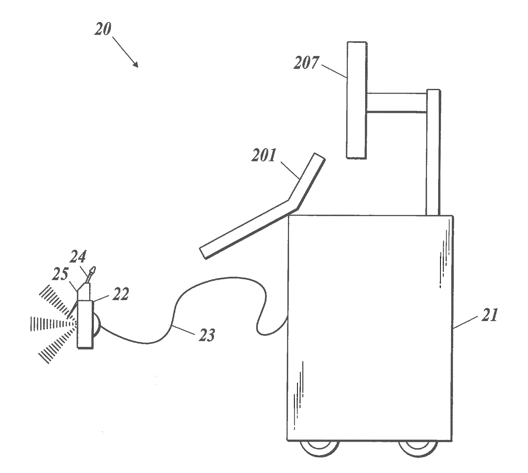
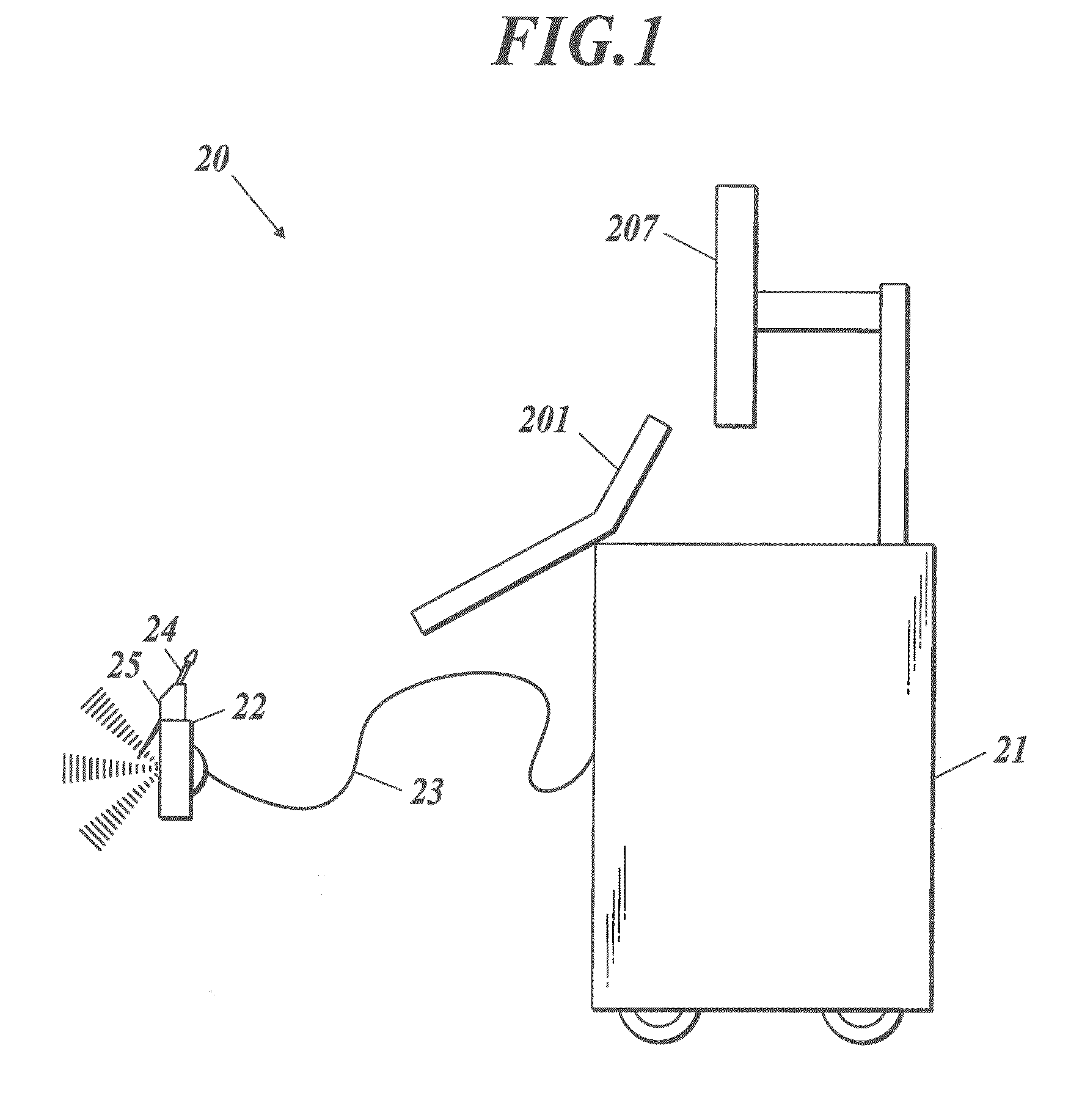
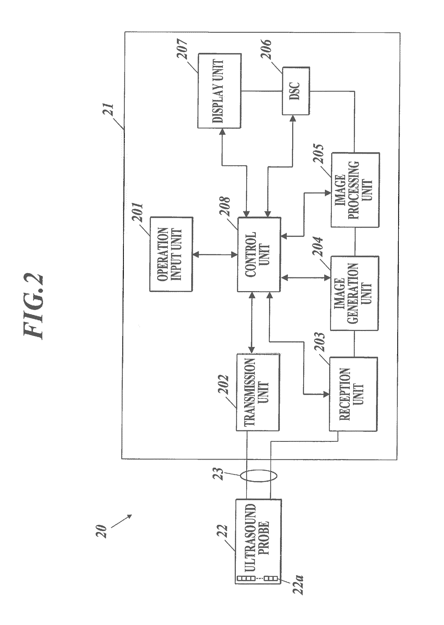
[0043]As shown in FIGS. 1 and 2, the ultrasound diagnostic imaging apparatus 20 according to an embodiment includes an ultrasound diagnostic imaging apparatus main body 21 and an ultrasound probe 22. The ultrasound probe 22 transmits ultrasound (transmission ultrasound) to a subject such as a living body (not shown in the drawing) and receives reflected wave (reflected ultrasound: echo) of the ultrasound reflected off the subject. The ultrasound diagnostic imaging apparatus main body 21 is connected with the ultrasound probe 22 via a cable 23. The ultrasound diagnostic ima...


PUM


Abstract

Disclosed is an ultrasound diagnostic imaging apparatus including an ultrasound probe which outputs transmission ultrasound to a subject according to a drive signal, a puncture needle being inserted in the subject, and which outputs a received signal obtained by receiving reflected ultrasound from the subject. The ultrasound diagnostic imaging apparatus further includes an image generation unit which generates ultrasound image data for each frame, a display unit which displays an ultrasound image, an evaluation information generation unit which generates movement evaluation information indicating movement evaluation between frames, a puncture needle position detection unit which detects a position of a tip of the puncture needle on a basis of the movement evaluation information, a highlighting unit which highlights display of a tip image in the ultrasound image and a speed calculation unit which calculates moving speed of the tip of the puncture needle.

Description

BACKGROUND OF THE INVENTION[0001]1. Field of the Invention[0002]The present invention relates to an ultrasound diagnostic imaging apparatus and an ultrasound image display method.[0003]2. Description of Related Art[0004]Biopsy where a puncture needle is inserted in a living body and where a piece of tissue or body fluid is obtained to make diagnosis has been performed. Here, in order not to insert the puncture needle at a different position in the living body by mistake when obtaining a predetermined tissue or the like, the puncture needle is to be attached to an ultrasound probe provided with an attachment or a guide, and an operator such as a physician makes an ultrasound image be displayed according to ultrasound image data of inside the living body obtained by the ultrasound probe and performs inserting of the puncture needle while confirming the inserting position by looking at the display.[0005]When performing insertion, in order to surely bring the puncture needle to the targ...

Claims


Application Information

Patent Timeline
Patent Type & Authority Applications(United States)
IPC IPC(8): A61B8/08A61B8/00
CPCA61B8/0841A61B8/5207A61B8/463A61B8/4405A61B8/5215A61B10/02A61B17/3403A61B34/20A61B2017/00075A61B2017/3413A61B2034/2065A61B2090/378G06T7/73G06T2207/10132G06T2207/30021G06T2207/30241G16H50/20A61B5/06A61B5/061A61B8/0833A61B8/14A61B8/4444A61B8/461G01S15/89G01S15/8915G06T7/0012G06T7/20G06T11/00
Inventor TAKEDA, YOSHIHIRO
Owner KONICA MINOLTA INC
Why Eureka
Try Eureka