Method for producing electrical component with multi-station progressive die

A component and multi-station technology, applied in the direction of forming tools, manufacturing tools, metal processing equipment, etc., can solve the problems of cumbersome work of replacing the mold head, complex mold mechanism, unsafety, etc., and achieve low manufacturing cost and short production time Fast and reduce labor intensity

Inactive Publication Date: 2010-04-28
SUZHOU RISING CREATION PRECISION TOOLS
View PDF0 Cites 15 Cited by
  • Summary
  • Abstract
  • Description
  • Claims
  • Application Information

AI Technical Summary

Benefits of technology

The technology described by this patented allows for continuous creating processes with only three steps: firstly, making sure that all necessary equipment are ready before starting another process; secondly, saving on time when working alongside other tasks or machines while still being able to use them effectively without having any extra effort from others. This saves money compared to traditional methods like manual assembly line inspections which require many hours' hands-on experience.

Problems solved by technology

This patented technical problem addressed in this patents relates to improving the performance and safety of diesel engine manufacturing while reducing downtime during changeover between different types of diesels due to the complexity involved when changing tools used for these operations.

Method used


Image

  • Method for producing electrical component with multi-station progressive die
  • Method for producing electrical component with multi-station progressive die
  • Method for producing electrical component with multi-station progressive die

Examples


Embodiment Construction

[0024] In order to make the technical means, creative features, goals and effects achieved by the present invention easy to understand, the present invention will be further described below in conjunction with specific illustrations.

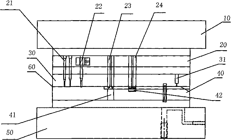
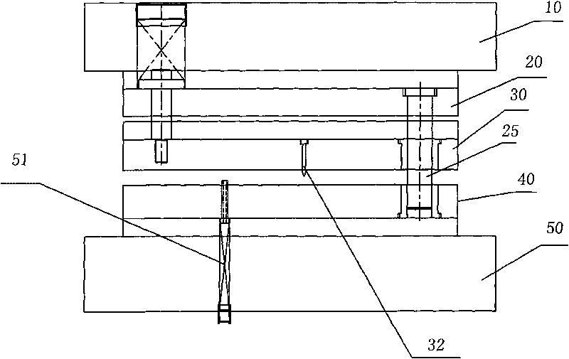
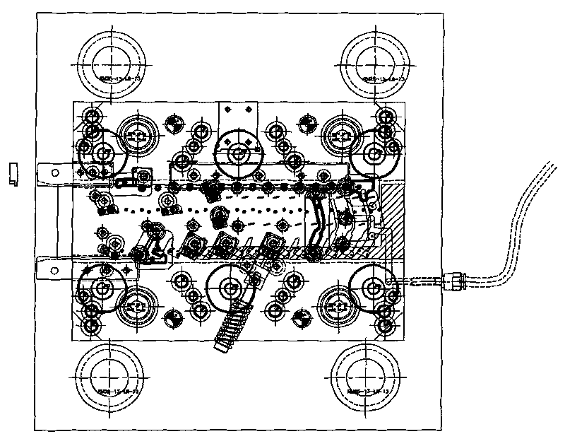
[0025] see figure 1 , figure 2 and image 3 , the electric parts mold of the present invention comprises an upper mold base 10, an upper backing plate 20, a punch fixing plate 30, a lower backing plate 40 and a material belt 60, and the material belt 60 is arranged on the punch fixing plate 30 and the lower backing plate 40 Between, the upper baffle plate 31 used for stripping and the stripper plate used for stripping; The inner guide post 25, the inner guide post 25 runs through the punch fixing plate 30 and is placed in the slot hole of the lower backing plate 40 to play the role of balancing the mould. The three layers of the upper mold base 10, the upper backing plate 20, and the punch fixing plate 30 are fixedly connected sequentially f...


PUM


Abstract

The invention discloses a method for producing an electrical component with a multi-station progressive die. The die comprises an upper die holder, an upper spacer plate, a punch fixing plate, a lower spacer plate and a material belt, wherein the die is internally provided with a plurality of groups of convex dies and concave dies with equal number and complementary shape, and the corresponding convex dies and concave dies are positioned on the punch fixing plate and the lower spacer plate according to the order of a punching technology; the die further comprises an inner guide pillar which is positioned on the upper spacer plate for balancing the die, a floating and opening dual-purpose pin positioned at one side of a lower die holder, and a guide needle positioned on the punch fixing plate; and the inner guide pillar is positioned in a slot hole of the lower spacer plate by penetrating through the punch fixing plate. The method completes multiple punching working procedures at the different positions of the material belt during one stroke of a punch according to a certain order, thereby continuously working and completing multiple working procedures without stopping the punch and replacing a die head.

Description


Claims


Application Information

Patent Timeline
Owner SUZHOU RISING CREATION PRECISION TOOLS
Why Eureka
Try Eureka