
Ink-jet recording device and ink cartridge

a technology of ink cartridges and recording devices, which is applied in printing and other directions, can solve the problems of inability to identify ink cartridges adapted to recording devices, inability to meet the needs of printing, and difficulty in identifying ink cartridges

Inactive Publication Date: 2008-05-06
SEIKO EPSON CORP
View PDF177 Cites 14 Cited by
  • Summary
  • Abstract
  • Description
  • Claims
  • Application Information

AI Technical Summary

Benefits of technology

[0011]The present invention is based on this problem, and an object of the invention is to provide an ink-jet recording device in which the number of kinds of shapes for judgment of adaptability can be increased by use of a relatively narrow space, and to provide an ink cartridge adapted to the ink-jet recording device.

Problems solved by technology

Hence, the former has a problem that the size or weight of the ink tank is increased by the volume of the porous member contained in the ink tank in comparison with the volume of ink capable of being contained in the ink tank.
The latter has a problem that the recording device is complicated in structure because a mechanism is required for preventing the change of ink pressure owing to vibration.
On the other hand, because the ink cartridge is formed as a rectangular parallelepiped container from the point of view of the structure, or the like, of the recording device, there is a problem that the ink cartridge adapted to the recording device can be hardly identified and may be selected by mistake.
If the weight of the ink cartridge, that is, the capacity thereof is reduced to make high-speed printing possible, there is however a problem that the number of kinds of recessed portions allowed to be formed in the narrow bottom portion of the ink cartridge is limited.

Method used


Image

  • Ink-jet recording device and ink cartridge
  • Ink-jet recording device and ink cartridge
  • Ink-jet recording device and ink cartridge

Examples


Embodiment Construction

[0052]The present invention will be described below in detail on the basis of various exemplary embodiments shown in the drawings.

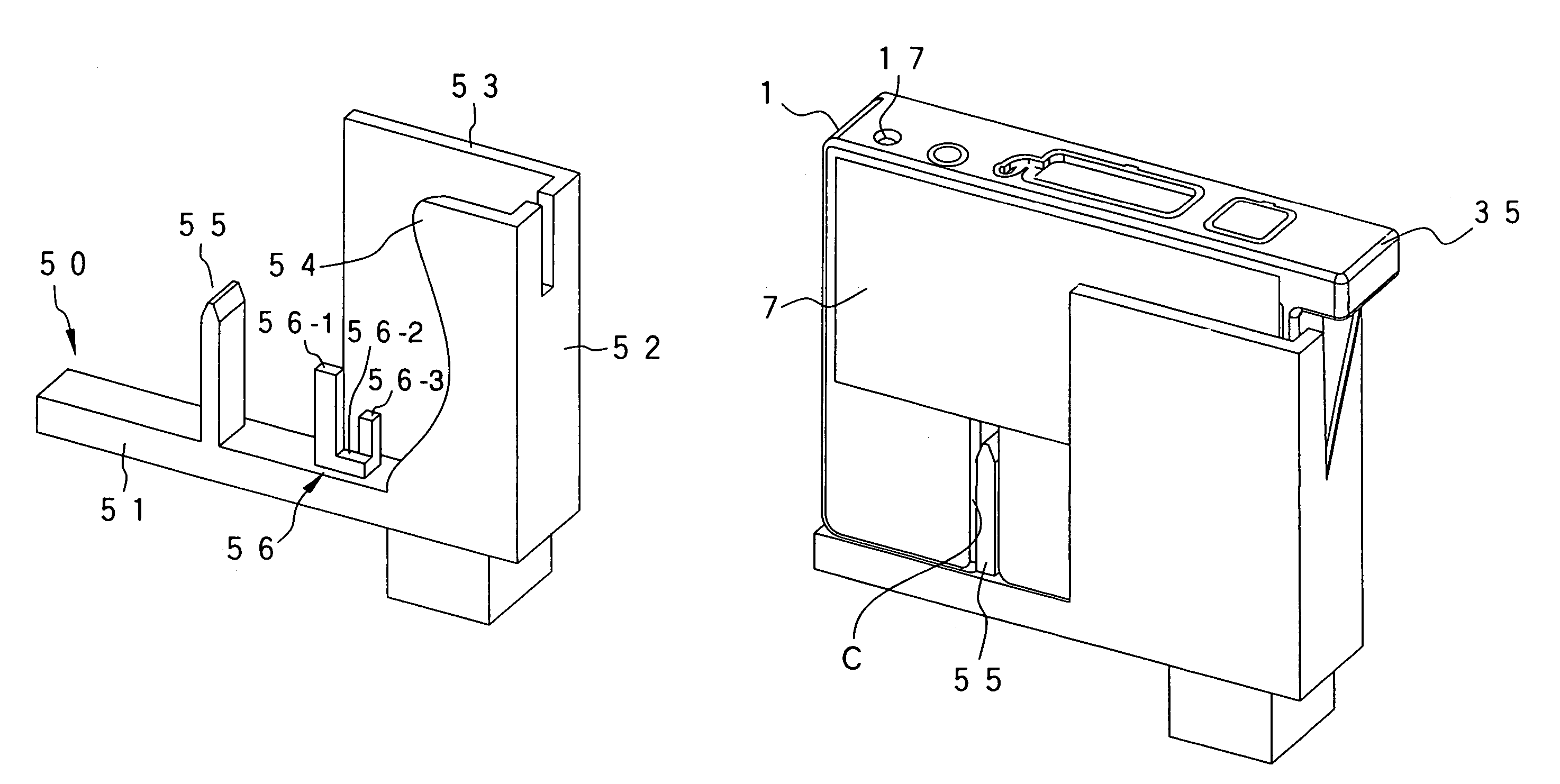
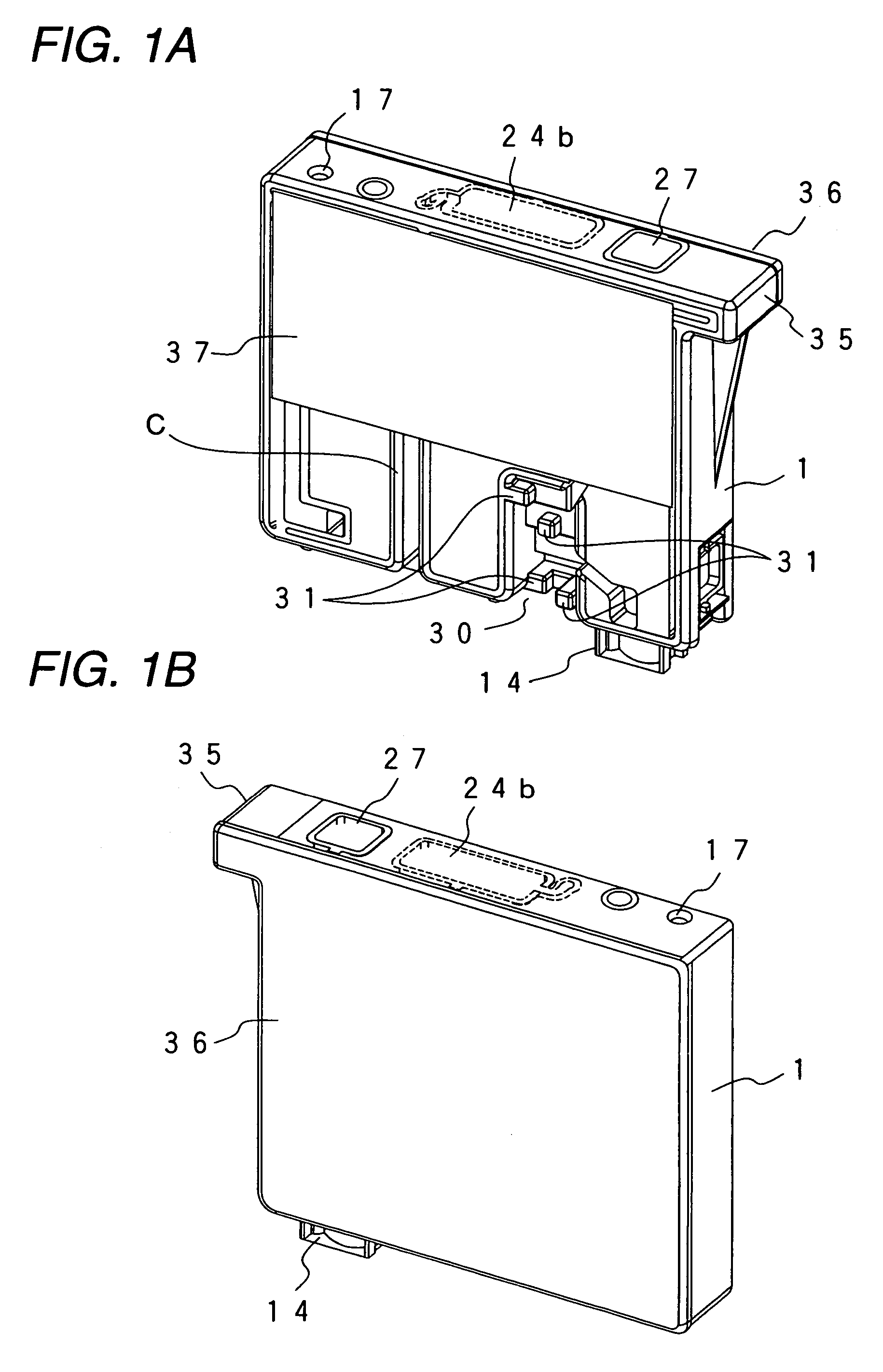
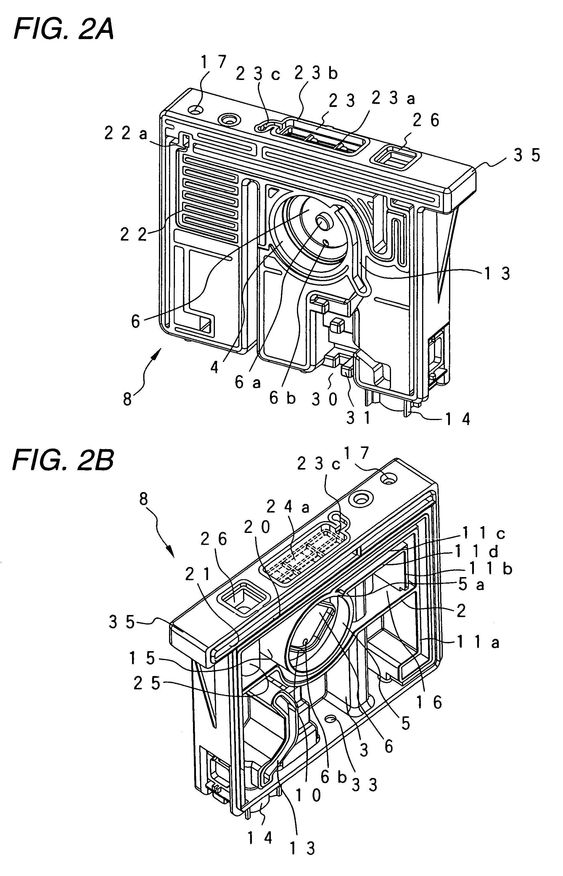
[0053]FIGS. 1A and 1B show an ink cartridge 1 according to one embodiment of the present invention. FIGS. 2A and 2B show the front and rear structures of a container body 8 constituting the ink cartridge 1. FIG. 3 shows the structure of the container body 8 viewed from the bottom surface thereof. The container body 8 is partitioned into upper and lower regions by a wall 2 (FIG. 2B)extended substantially horizontally. A first ink chamber 3 is formed in the lower region. A differential pressure valve-storing chamber 4 (FIG. 2A) which serves as a negative pressure generating mechanism which will be described later, a filter chamber 5 for storing a filter, and second and third ink chambers 15 and 16 are formed in the upper region.

[0054]The differential pressure valve-storing chamber 4 and the filter chamber 5 are separated from each other in a direction of th...


PUM


Abstract

An ink-jet recording device for supplying ink to a recording head from at least one ink cartridge having a bottom wall, and first and second side walls connected to each other through the bottom wall and facing each other, the ink cartridge further having an ink supply port at the bottom wall, a first retaining member extending from the first side wall and a recess provided in the vicinity of the second side wall, the retaining member having a first engagement portion displaceable toward and away from the first side wall. The recording device comprises a carriage having at least one ink cartridge mounting region adapted to receive the ink cartridge, a plurality of one identification members that are protruded from a bottom of the ink cartridge mounting region in a direction parallel to an insertion direction of the ink cartridge into the carriage, and that are positioned and configured so that the identification members are received by the recess of the ink cartridge when the ink cartridge is compatible to the ink cartridge mounting region; an ink supply needle positioned in the bottom of the ink cartridge storage region and configured for connection to the ink supply port of the ink cartridge, and a first engagement portion positioned and configured to engage the engagement portion of the ink cartridge.

Description

CROSS-REFERENCE TO RELATED APPLICATION[0001]This application is a continuation of U.S. patent application Ser. No. 10 / 045,933, entitled Ink Jet Recording Device and Ink Cartridge, filed Oct. 19, 2001 now U.S. Pat. No. 6,722,762, the contents of which are hereby incorporated by reference herein.BACKGROUND OF THE INVENTION[0002]The present invention relates to a technique for identifying an ink cartridge which supplies ink at an appropriate negative pressure to a recording head which ejects ink droplets in response to print signals.[0003]An ink-jet recording device is usually configured so that an ink-jet recording head for ejecting ink droplets in response to print signals is mounted on a carriage which makes reciprocating motion in a direction of the width of a recording sheet, and so that ink is supplied from an external ink tank to the recording head. In the recording head of a small-size type, an ink storage container such as an ink tank or the like is detachably attached to the ...

Claims


Application Information

Patent Timeline
IPC IPC(8): B41J2/14B41J2/175
CPCB41J2/17503B41J2/17509B41J2/17513B41J2/1752B41J2/17526B41J2/1755B41J2/17553B41J2/17556B41J2/17596B41J2/17563B41J2/175
Inventor MIYAZAWA, HISASHISHINADA, SATOSHISAKAI, YASUTO
Owner SEIKO EPSON CORP
Learn More