Radio base station apparatus, radio terminal apparatus and wireless communication method

a radio terminal and base station technology, applied in the field of radio terminal apparatus, radio communication method, can solve problems such as unsatisfactory reception characteristics, and achieve the effects of reducing the amount of feedback information, improving the reception characteristics of the terminal located near the edge of the cell, and accurately determining the transmission schem

Active Publication Date: 2012-07-05
PANASONIC INTELLECTUAL PROPERTY MANAGEMENT CO LTD
View PDF4 Cites 31 Cited by
  • Summary
  • Abstract
  • Description
  • Claims
  • Application Information

AI Technical Summary

Benefits of technology

[0020]According to the base station, the terminal, and the radio communication method of the invention, the base station allocates some of all the frequency bands to bands used for single base station transmission (the first transmission scheme) and allocates some of all the frequency bands to bands used for plural base station transmission (the second transmission scheme). Then, the base station receives the feedback information indicating the reception quality of some of all the frequency bands used for the first or second transmission scheme, and determines which the transmission scheme is used based on the feedback information. Accordingly, since the feedback information can be restricted to the information indicating the reception quality of some of all the frequency bands, the amount of feedback information can be reduced. Further, since the feedback information indicates the reception quality of one of the bands for the first transmission scheme and the bands for the second transmission scheme, the information indicating both transmission schemes may not coexist unlike the conventional technique and the transmission scheme can be accurately determined.
[0021]Thus, even when the single base station transmission and the CoMP transmission are simultaneously executed, the reception characteristics of the terminal located near the edge of the cell can be improved by reducing the amount of feedback information given from the terminal to the base station and reducing the ICI.

Problems solved by technology

In the conventional technique, the single base station transmission is applied to a terminal (for example, a terminal located near the center of the cell) having satisfactory reception characteristics and the CoMP transmission is applied to a terminal (a terminal located near the edge of the cell) being largely affected by ICI and thus having unsatisfactory reception characteristics.

Method used


Image

  • Radio base station apparatus, radio terminal apparatus and wireless communication method
  • Radio base station apparatus, radio terminal apparatus and wireless communication method
  • Radio base station apparatus, radio terminal apparatus and wireless communication method

Examples


embodiment 1

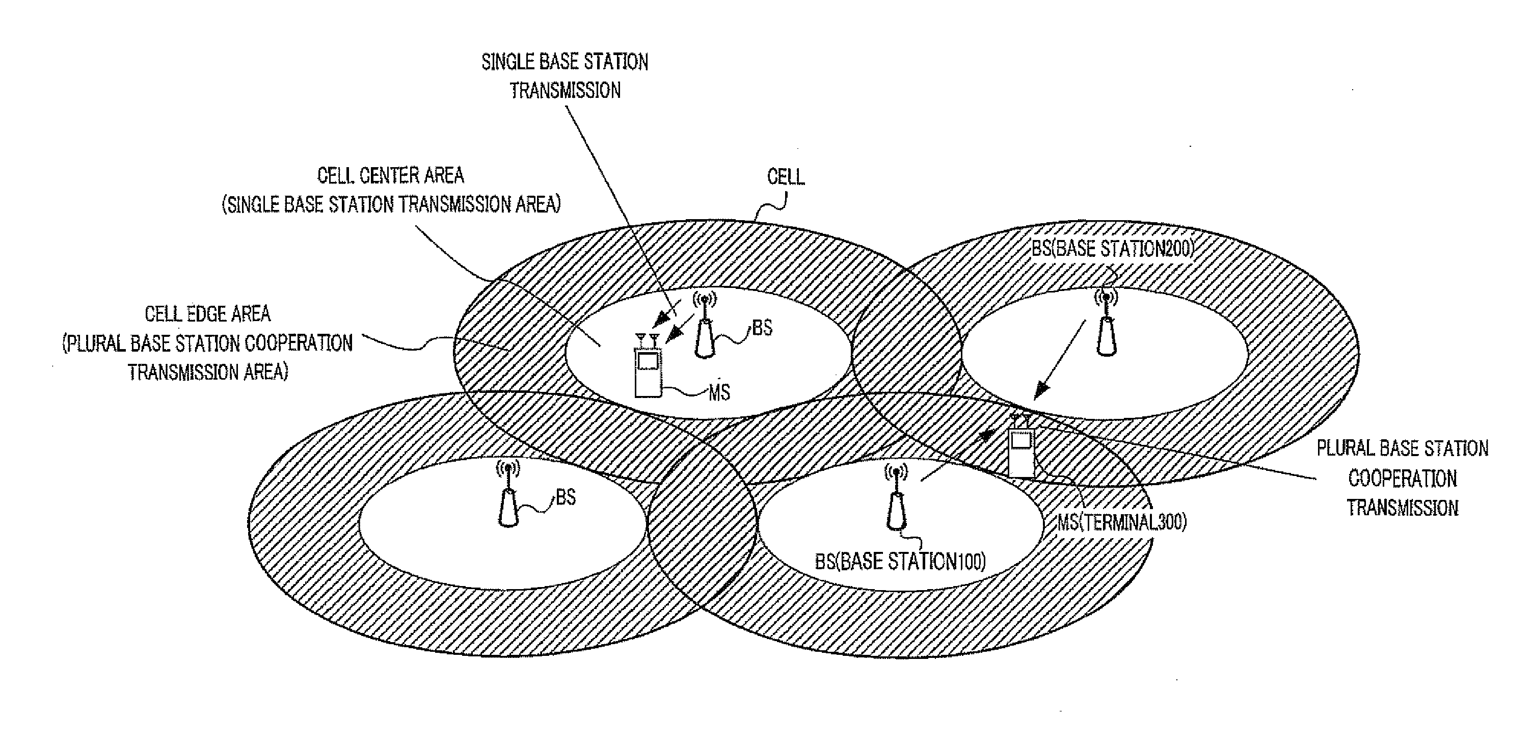
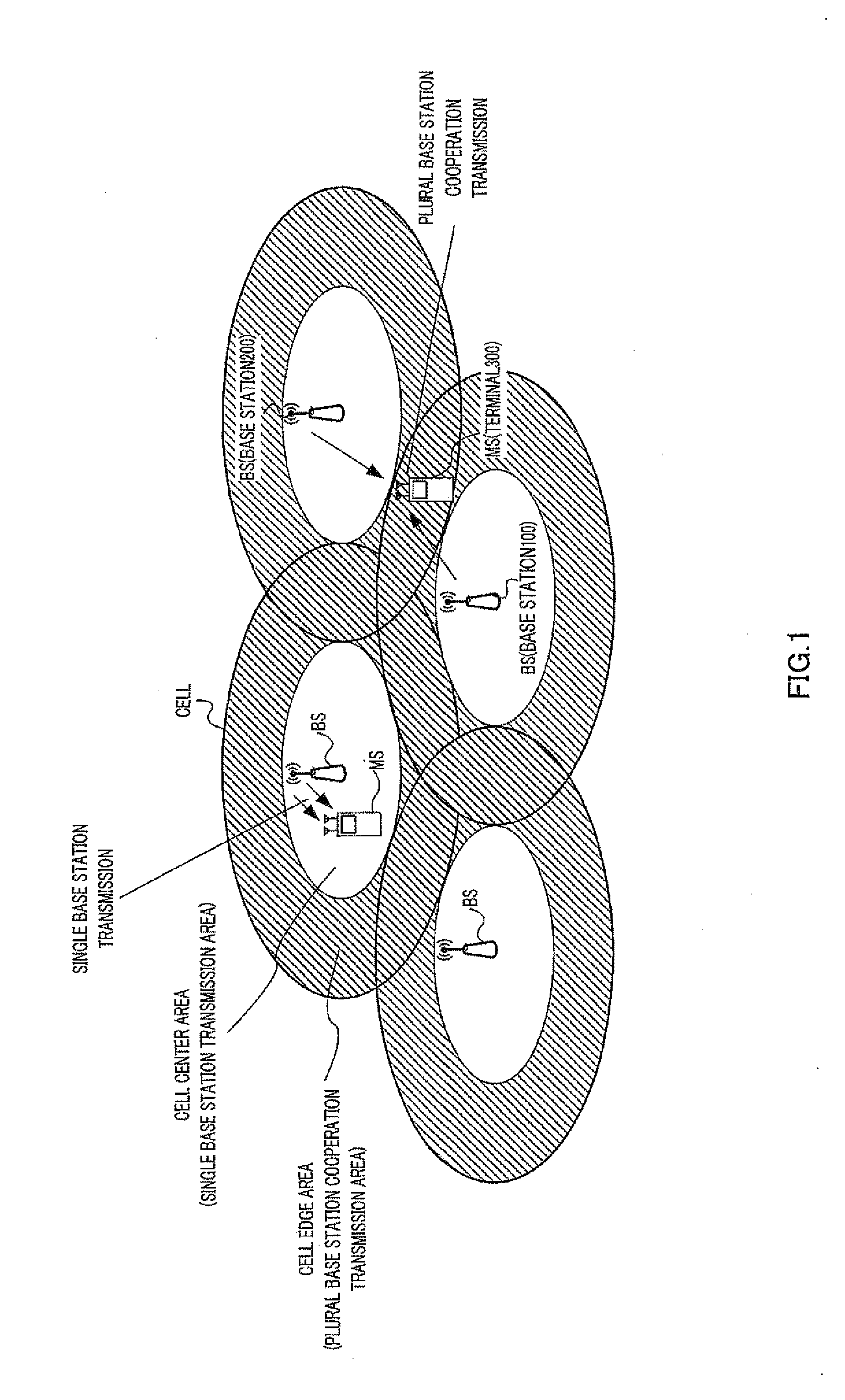
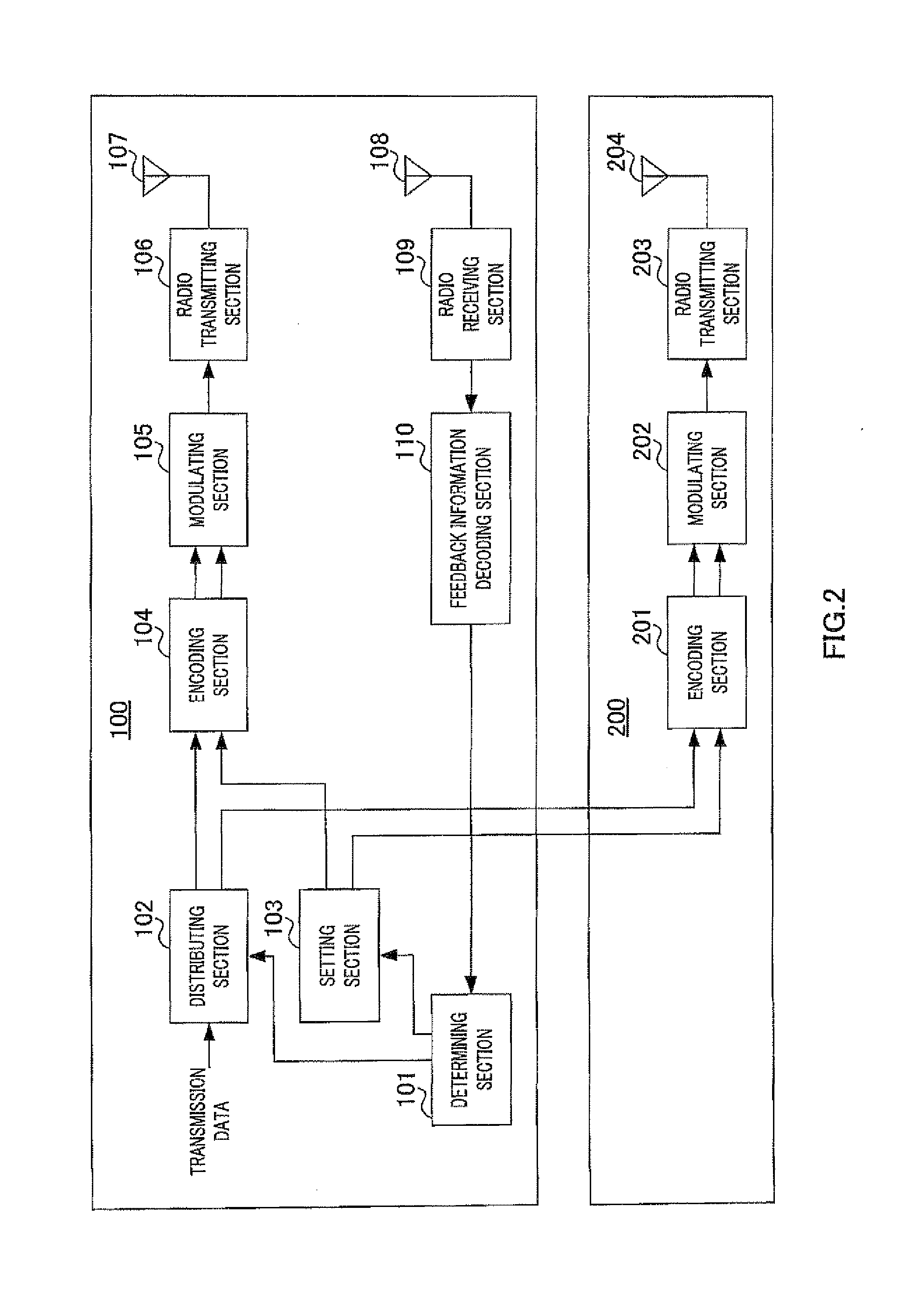
[0047]FIG. 2 illustrates the configurations of base stations 100 and 200 of the radio communication system (see FIG. 1) according to this embodiment. FIG. 3 illustrates the configuration of terminal 300. Here, a base station (base station 100 in FIG. 1) covering an area where a terminal (terminal 300 in FIG. 1) is present is referred to as a master base station (or also referred to as a serving cell). Another base station (base station 200 in FIG. 1) executing the CoMP transmission along with the master base station is referred to as a slave base station (or also referred to as a neighbor cell). Base station 100 serving as the master base station notifies base station 200 serving as the slave base station of control information regarding a frequency band allocable for transmission data.

[0048]In base station 100 (the master base station) illustrated in FIG. 2, determining section 101 determines one of the single base station transmission and the CoMP transmission as a transmission sc...

embodiment 2

[0079]In this embodiment, a ratio (hereinafter, referred to as a frequency band ratio) between the bandwidth of the frequency bands used for the single base station transmission and the bandwidth of the frequency bands used for the CoMP transmission in the system band is set to be variable. The frequency band ratio is fixed in Embodiment 1. However, in this embodiment, the frequency band ratio is variable to construct the system capable of executing flexible control in accordance with the communication state with the terminal.

[0080]In this embodiment, setting section 103 (see FIG. 2) of base station 100 receives the number of terminals (hereinafter, referred to as the number of cell edge terminals) located in the cell edge area of base station 100 illustrated in FIG. 1, and the number of terminals (hereinafter, referred to as the number of cell center terminals) located in the cell center area of base station 100 illustrated in FIG. 1 (or receives a ratio of the number of cell edge ...


PUM


Abstract

A radio base station apparatus wherein even when a single-base-station transmission and a plural-base-station cooperative transmission are implemented at the same time, the terminal-to-base-station feedback information amount and the ICI can be reduced, thereby improving the reception characteristic of a terminal existing in the vicinity of a cell edge. A base station (100) uses a first transmission mode, in which only the base station implements a signal transmission, and a second transmission mode, in which the base station implements a cooperative signal transmission together with another radio base station apparatus, to communicate with one or more radio terminal apparatuses. A setting unit (103) sets, as a particular frequency band the reception quality of which is to be measured, one of first and second frequency bands that are parts of a band used for communications with the terminals. A deciding unit (101) decides, as the transmission mode for the terminals, one of the first and second transmissions on the basis of the reception quality of the particular frequency band.

Description

TECHNICAL FIELD[0001]The present invention relates to a radio base station apparatus, a radio terminal apparatus, and a radio communication method.BACKGROUND ART[0002]In a cellular system represented by a cellular phone, a cell refers to a range in which a radio base station apparatus (hereinafter, simply referred to as a base station (BS)) can communicate with a radio terminal apparatus (hereinafter, simply referred to as a mobile station (MS) or user equipment (UE)), that is, a range (communication area) that the base station covers. In the cellular system, the communication area is extensively expanded by disposing a plurality of base stations.[0003]In the cellular system, the same frequencies are repeatedly used between the cells to efficiently utilize finite frequency resources. For example, in the cellular system, a system band is divided into N frequency bands, and the N frequency bands are used in such a manner that the same frequency is not used by N adjacent cells (N-cell ...

Claims


Application Information

Patent Timeline
Patent Type & Authority Applications(United States)
IPC IPC(8): H04W72/04
CPCH04B7/024H04B7/0658H04L5/0035H04W88/06H04W28/04H04W28/06H04W24/10
Inventor SEKI, YUTA
Owner PANASONIC INTELLECTUAL PROPERTY MANAGEMENT CO LTD
Why Eureka
Try Eureka