
System and method for treating arrhythmias in the heart using information obtained from heart wall motion

Active Publication Date: 2012-07-05
RYU KYUNGMOO +8
View PDF6 Cites 78 Cited by
  • Summary
  • Abstract
  • Description
  • Claims
  • Application Information

AI Technical Summary

Benefits of technology

[0010]A system and method in accordance with the present teachings are advantageous because the system and method provide an effective measure of the effectiveness of ablation therapy. In particular, the motion of the position sensors is used to infer motion of the cardiac tissue and this motion can be used to assess the impact of ablation therapy during or after administration of the therapy. For example, a lack of motion in certain tissues may indicate that an electrical pathway has been effectively severed and the treatment successful. Motion of certain tissues may also provide an indication of a change in blood flow between the atrial and ventricular chambers resulting from the ablation therapy such that an optimal pos-operative anticoagulation regimen can be determined. The inventive system and method therefore enable a clinician to better assess the efficacy and safety of ablation therapy.

Problems solved by technology

Arrhythmia can create a variety of dangerous conditions including irregular heart rates, loss of synchronous atrioventricular contractions and stasis of blood flow which can lead to a variety of ailments and even death.
There are, however, a number of risks associated with ablation therapy including reduced contribution by atria to ventricular filling, stagnation of blood in the atria leading to a hematoma or thrombus, cavitation of blood resulting from heating during ablation which can result in creation of an embolus or thrombus, and coagulation of blood resulting from the presence of a foreign object (i.e., the ablation catheter) which can result in creation of a thrombus.

Method used


Image

  • System and method for treating arrhythmias in the heart using information obtained from heart wall motion
  • System and method for treating arrhythmias in the heart using information obtained from heart wall motion
  • System and method for treating arrhythmias in the heart using information obtained from heart wall motion

Examples


Embodiment Construction

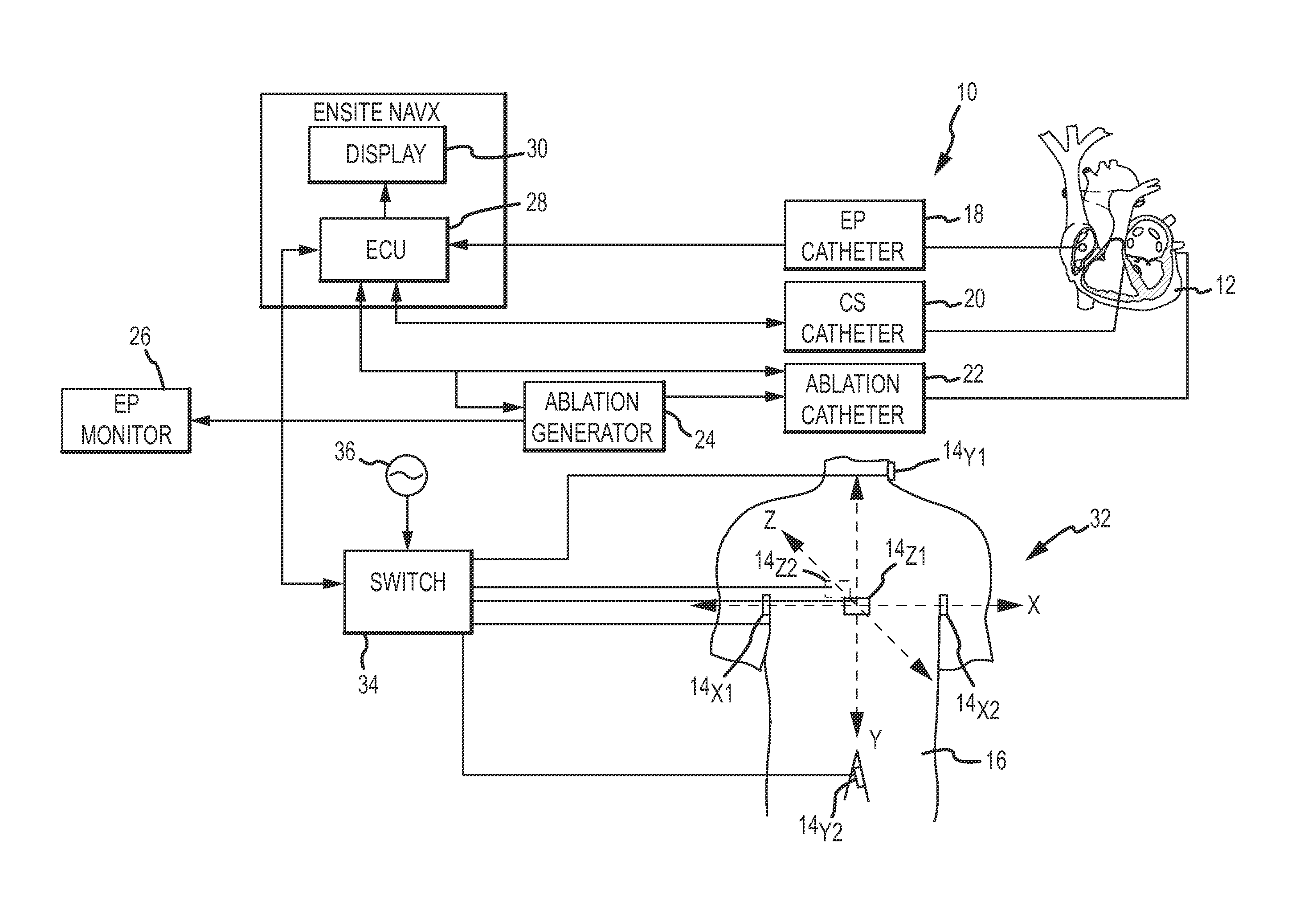
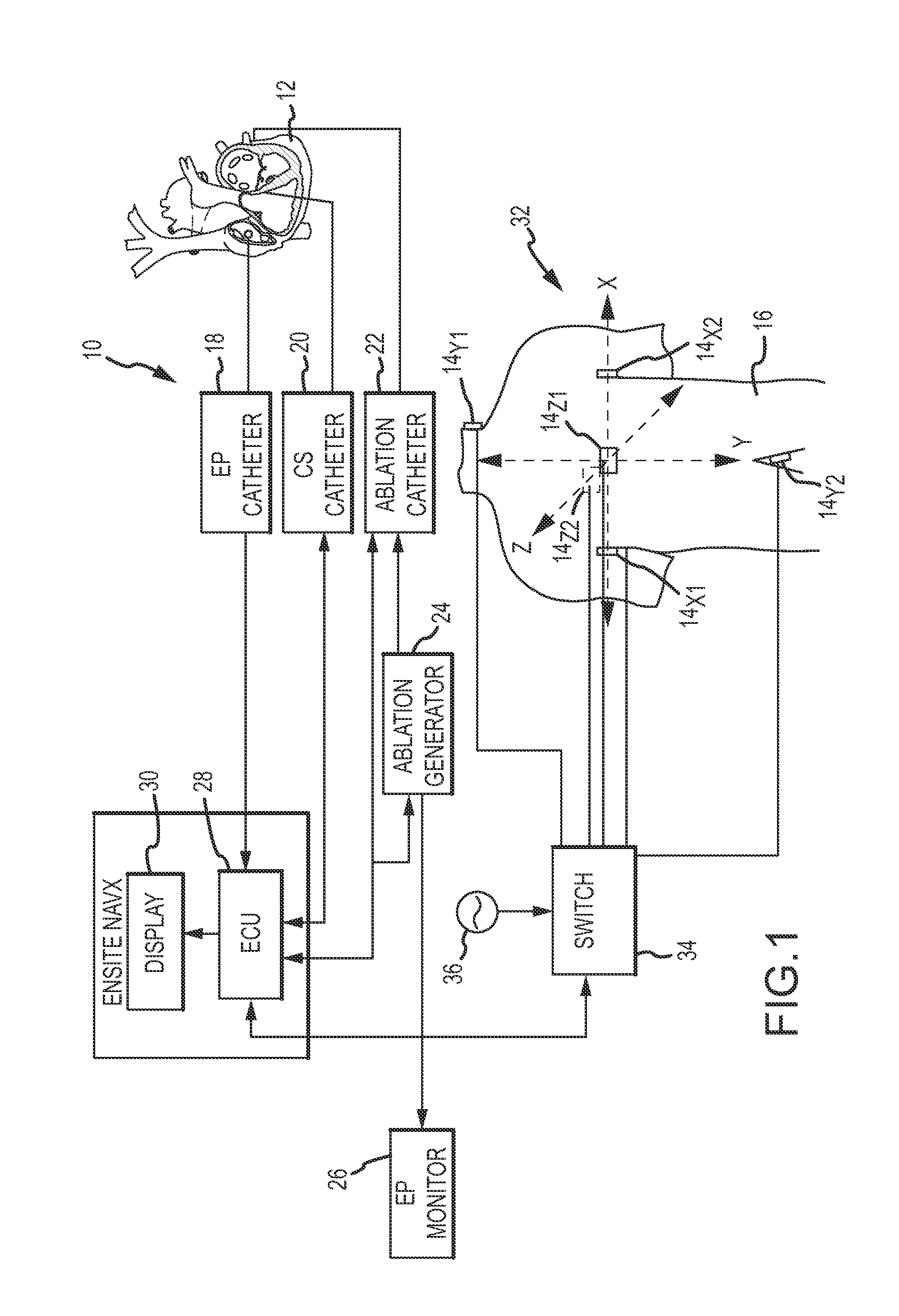
[0017]Referring now to the drawings wherein like reference numerals are used to identify identical components in the various views, FIG. 1 illustrates one embodiment of a system 10 for treatment of an arrhythmia of a heart 12 in accordance with the present teachings. System 10 may include a plurality of patch electrodes 14 applied to the surface of the body 16, a plurality of catheters including electrophysiological (EP) catheter 18, coronary sinus (CS) catheter 20 and ablation catheter 22, an ablation generator 24, an EP monitor 26, an electronic control unit (ECU) 28 and a display 30.

[0018]Patch electrodes 14 can generate or receive electrical signals which can be used in determining the position of catheters 18, 20, 22 within a three dimensional coordinate system 32 and to generate EP data regarding heart 12. Electrodes 14 are made from flexible, electrically conductive material and are configured for affixation to body 16 such that electrodes 14 are in electrical contact with th...


PUM


Abstract

A system and method for treating an arrhythmia in a heart are provided. The system includes an electronic control unit configured to monitor movement of one or more position sensor over a period of time. The position sensors may, for example, comprise electrodes or coils configured to generate induced voltages and currents in the presence of electromagnetic fields. The positions sensors are in contact with portions of heart tissue and changes in position are representative of motion of that tissue. The electronic control unit is further configured to generate an indicator, responsive to the movements of the sensors over the period of time, of a characteristic of the heart affected by delivery of ablation energy to heart tissue. In this manner, the effectiveness and safety of cardiac tissue ablation for treatment of the arrhythmia can be assessed and a post-ablation therapy regimen determined.

Description

BACKGROUND OF THE INVENTION[0001]a. Field of the Invention[0002]This invention relates to a system and method for treating arrhythmias in the heart. In particular, the instant invention relates to a system and method that monitor movement of position sensors on heart tissue to generate indicators of various characteristics of the heart affected by the delivery of ablation energy.[0003]b. Background Art[0004]It is well known to use ablation catheters to create tissue necrosis in cardiac tissue to correct cardiac arrhythmias (including, but not limited to, atrial fibrillation, atrial flutter, atrial tachycardia and ventricular tachycardia). Arrhythmia can create a variety of dangerous conditions including irregular heart rates, loss of synchronous atrioventricular contractions and stasis of blood flow which can lead to a variety of ailments and even death. It is believed that the primary cause of many arrhythmias is stray electrical signals within one or more heart chambers. The ablat...

Claims


Application Information

Patent Timeline
IPC IPC(8): A61B18/14
CPCA61B5/1107A61N7/022A61B18/1206A61B18/1492A61B18/20A61B2018/00375A61B2018/00577A61B2018/00642A61B2018/00666A61B2018/00702A61B2018/00726A61B2018/00744A61B2018/0088A61B2018/0212A61B2019/5251A61B2218/002A61B18/082A61B8/488A61B34/20A61B2018/00351A61B2018/00863A61B2018/00892A61B2034/2051A61B2034/2059
Inventor RYU, KYUNGMOONGO, THAO T.PARK, EULJOONROSENBERG, STUARTKEEL, ALLENHOU, WENBOKOH, STEVENOREN, KJELLYANG, MICHAEL
Owner RYU KYUNGMOO
Learn More