
Buttress plate system

a buttress plate and plate body technology, applied in the field of buttress plate systems, can solve the problems of inadvertent back out or displacement of intervertebral spacers, pain in the back and lower extremities,

Inactive Publication Date: 2012-07-05
SPINAL USA
View PDF19 Cites 13 Cited by
  • Summary
  • Abstract
  • Description
  • Claims
  • Application Information

AI Technical Summary

Benefits of technology

[0010]In some embodiments, a spinal implant system comprising an intervertebral spacer, buttress plate and insertion instrument is provided. The intervertebral space is configured and arranged to be positioned in an intervertebral space between a first vertebra and a second vertebra of a patient. The buttress plate includes a plate body configured and arranged to extend across at least a portion of the intervertebral space and at least inhibit the intervertebral spacer from backing out when the buttress plate is connected to at least one vertebra. The buttress plate further includes an aperture for receiving a screw. The insertion instrument includes a proximal portion, a distal portion and a sleeve there between, wherein the distal portion of the insertion instrument is configured to couple to the buttress plate. The insertion instrument is configured to guide the screw through the sleeve to the aperture of the buttress plate when the buttress plate is coupled to the insertion instrument.

Problems solved by technology

This causes the spinal disc to lose its cushioning ability and ability to bear loads, resulting in pain in the back and lower extremities.
In some circumstances, following implantation, these intervertebral spacers can inadvertently back out or be displaced from an intervertebral space.

Method used


Image

  • Buttress plate system
  • Buttress plate system
  • Buttress plate system

Examples


Embodiment Construction

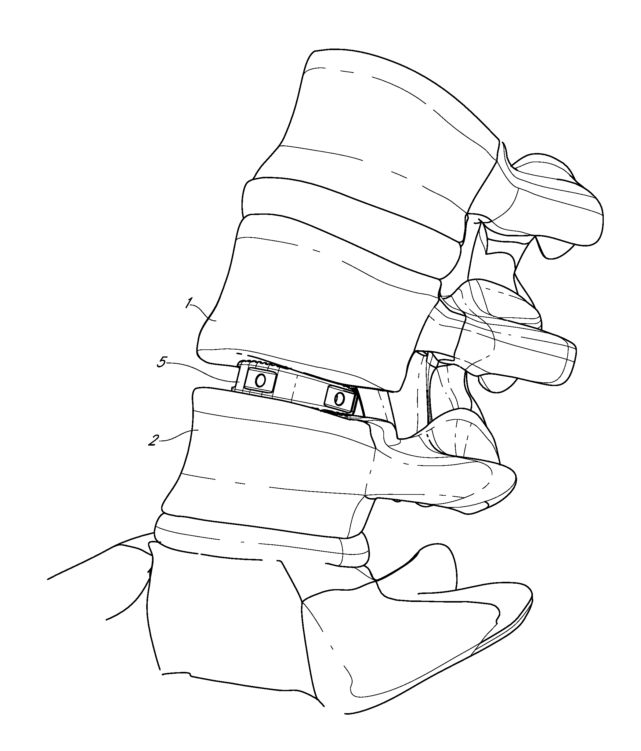
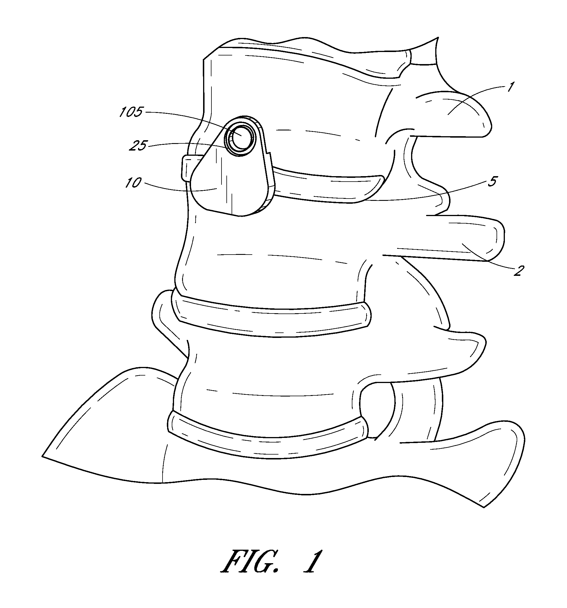
[0008]The present application relates to devices, systems and processes for spinal surgeries. In particular, the present application relates to a buttress plate that can be positioned across an intervertebral space to prevent a spacer from unintentionally backing out of an intervertebral space.

[0009]In some embodiments, a spinal implant system comprising an intervertebral spacer, buttress plate, screw and insertion instrument is provided. The intervertebral spacer is configured and arranged to be positioned in an intervertebral space between a first vertebra and a second vertebra of a patient. The buttress plate includes a plate body configured and arranged to extend across at least a portion of the intervertebral space to at least inhibit the intervertebral spacer from backing out from the intervertebral space when the buttress plate is connected to at least one vertebra. The buttress plate further includes a top surface and a bottom surface, wherein the bottom surface includes at ...


PUM


Abstract

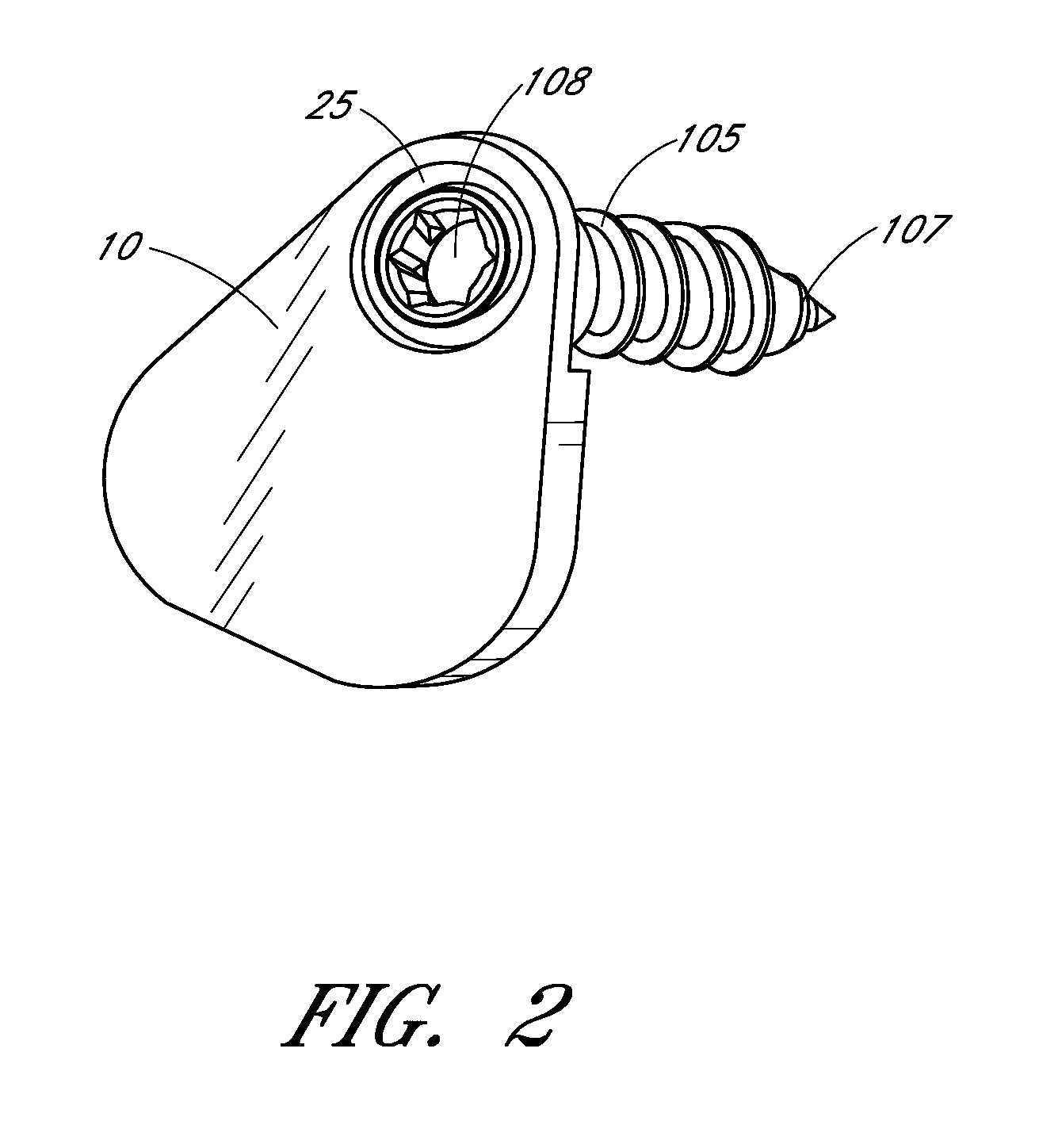
Systems, devices and methods are provided for assisting in spinal stabilization. A buttress plate system is provided that can include an intervertebral spacer, a buttress plate, a spinal screw, and an insertion instrument. The buttress plate is configured to extend across at least a part of an intervertebral space to block or prevent an intervertebral spacer from backing out of the intervertebral space when the buttress plate is secured to the spine. The buttress plate includes a curved plate body having an aperture therethrough for receiving a spinal screw. The buttress plate also includes a pair of engagement members in the form of spikes to help stabilize the buttress plate relative to the spine prior to securing the buttress plate to the spine. The buttress plate can be coupled to an insertion instrument that is used to guide the buttress plate to a desired position adjacent the spine. Once in a desired position, a spinal screw can be delivered through the insertion instrument and through the aperture of the buttress plate to secure the buttress plate to the spine. The insertion instrument thus helps to properly position the buttress plate adjacent the spine and to deliver a spinal screw toward the aperture of the buttress plate.

Description

BACKGROUND OF THE INVENTION[0001]1. Field of the Invention[0002]The present application relates to devices, systems and processes for spinal surgeries. In particular, the present application relates to devices, systems and processes for disc replacement surgeries.[0003]2. Description of the Related Art[0004]The spine relies on intervertebral spinal discs in between adjacent vertebrae to serve as mechanical cushions and to transmit compressive loads. Spinal discs are composed of an outer annulus fibrosus that surrounds an inner nucleus pulposus. The annulus fibrosus is composed of laminae of fibrous tissue and fibrocartilage, while the nucleus pulposus is composed of water, chondrocytes, collagen fibrils and proteoglycan aggrecans that have hyaluronic long chains. The nucleus pulposus functions to distribute hydraulic pressure in all directions within each disc under compressive loads.[0005]The nucleus pulposus, which begins early in life as eighty percent water, slowly dessicates wi...

Claims


Application Information

Patent Timeline
IPC IPC(8): A61F2/44A61B17/88A61B17/70
CPCA61B17/7059A61B17/809A61B17/808
Inventor PHILLIPS, JAMES MILTONDICKERMAN, ROBBIE DALE
Owner SPINAL USA
Learn More