Control device of inverted pendulum type vehicle

a control device and inverted pendulum technology, applied in vehicle position/course/altitude control, process and machine control, instruments, etc., can solve the problems of large vehicle volume, complicated vehicle structure, and difficulty in maintaining the payload support part substantially constant angl

Active Publication Date: 2012-07-05
HONDA MOTOR CO LTD
View PDF8 Cites 15 Cited by
  • Summary
  • Abstract
  • Description
  • Claims
  • Application Information

AI Technical Summary

Benefits of technology

[0027]According thereto, for the first direction, the manipulated variable for control is determined so as to make the representative point velocity converge at the desired velocity variably adjusted according to the component of the external force in the first direction; and for the second direction, the desired velocity being zero to prevent the vehicle from inclining toward the second direction, enabling the pedestrian or the like to move the vehicle smoothly at a desired velocity.

Problems solved by technology

Therefore, it is difficult to maintain the payload support part at a substantially constant angle so as to move the vehicle toward the desired moving direction smoothly.
It is reasonable that it may be considered to dispose training wheels in the vehicle to allow the vehicle moving smoothly; however, it will make the structure of the vehicle complicated and the entire vehicle large-scaled, which makes it inapplicable.

Method used


Image

  • Control device of inverted pendulum type vehicle
  • Control device of inverted pendulum type vehicle
  • Control device of inverted pendulum type vehicle

Examples


Embodiment Construction

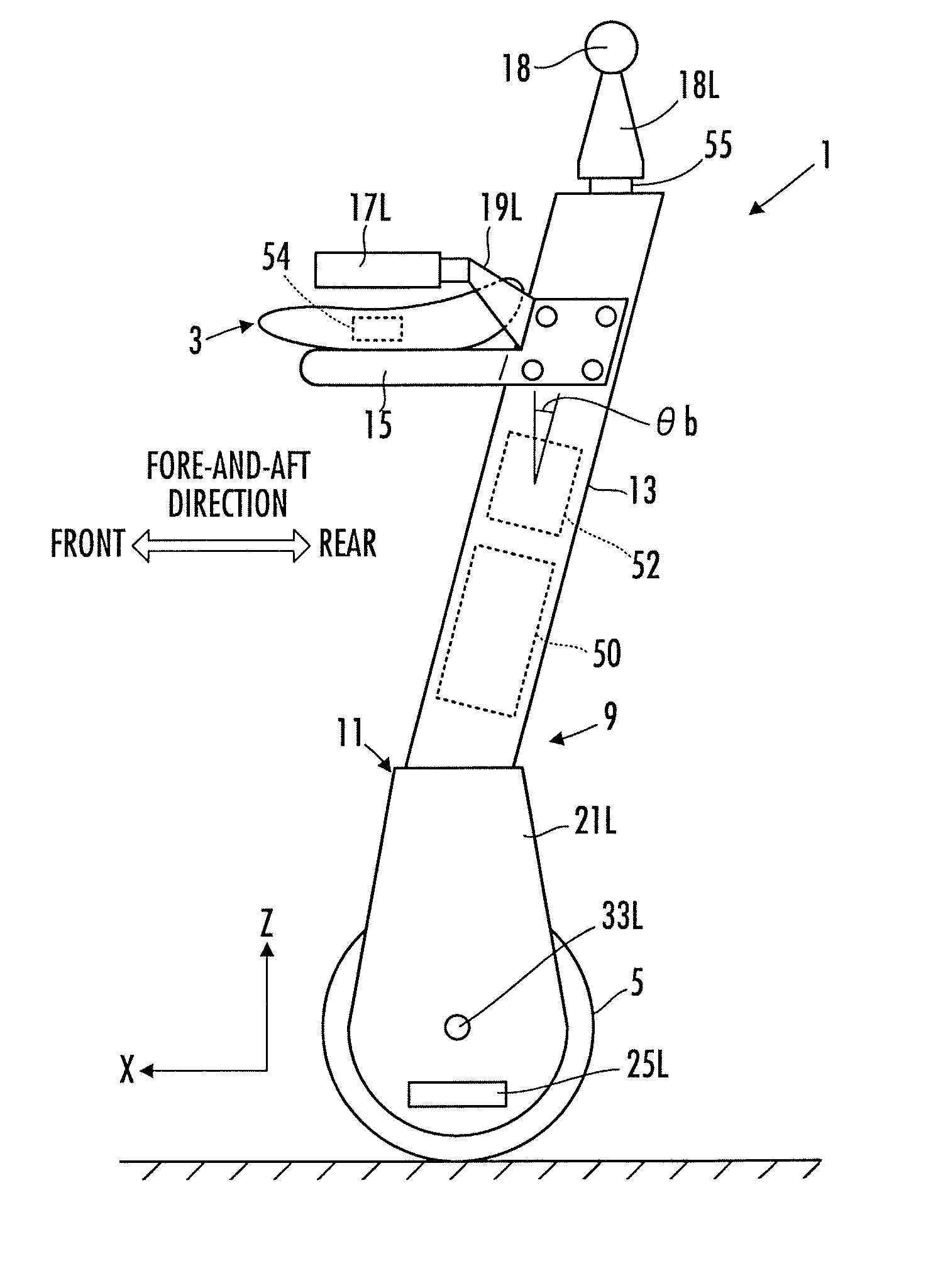
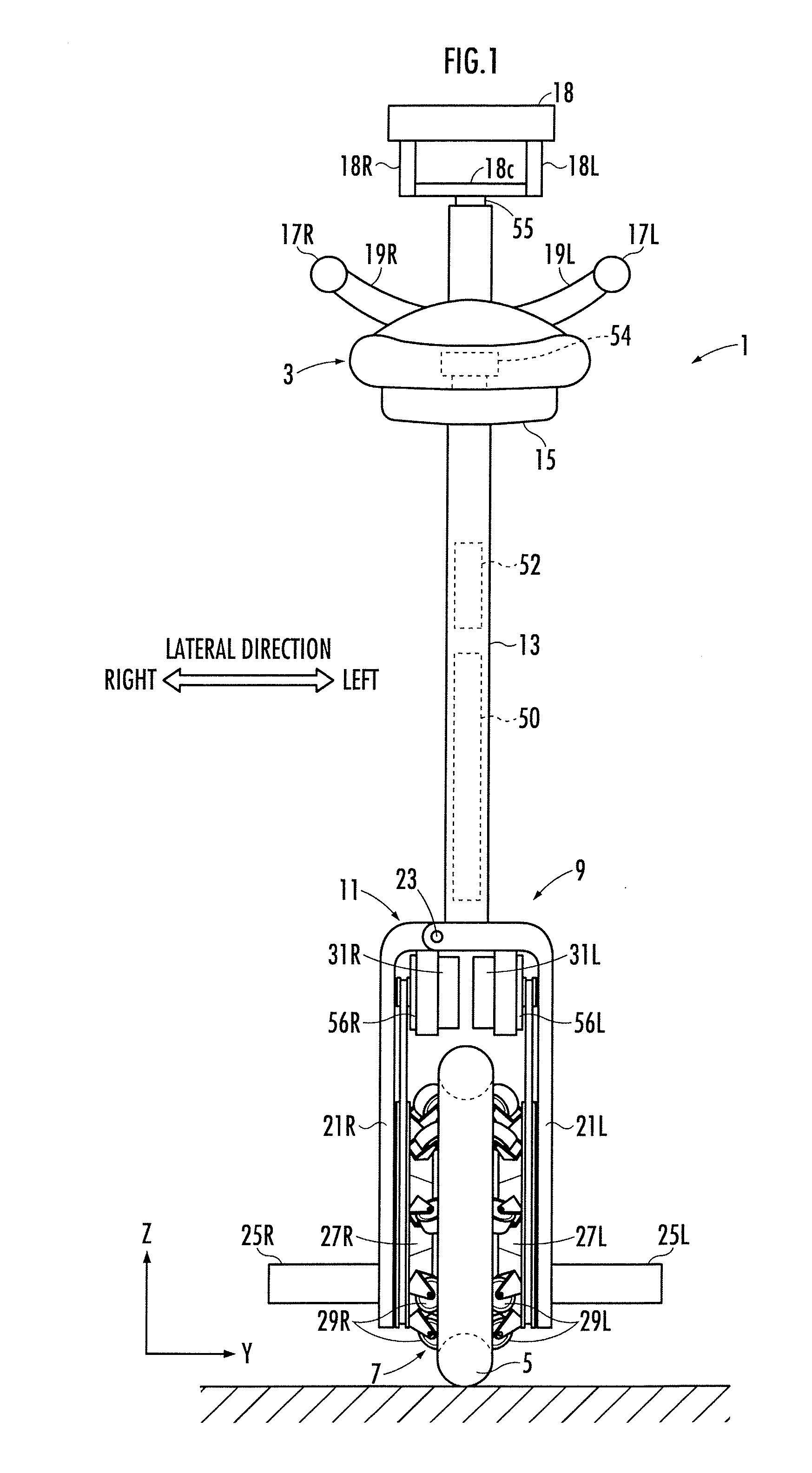
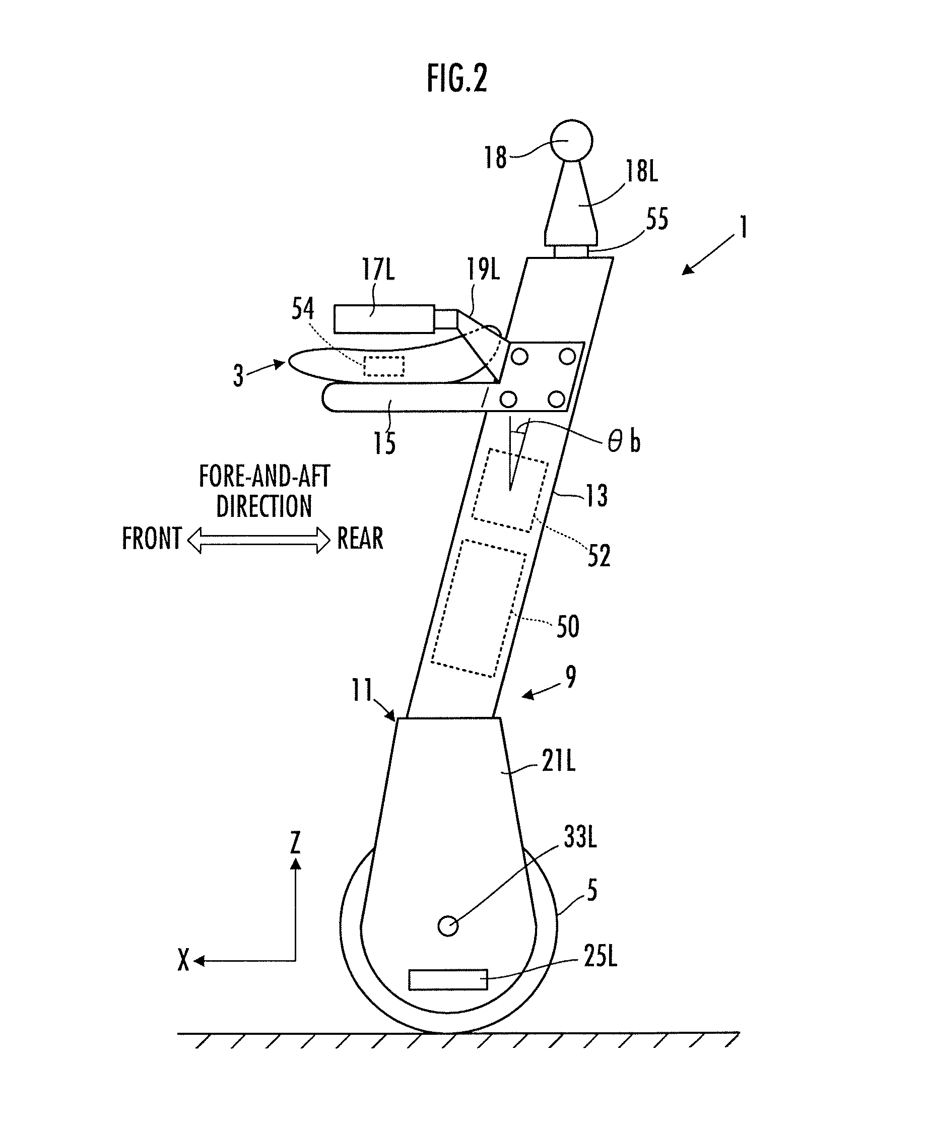
[0043]A first embodiment of the present invention will be described hereinafter. First, referring to FIG. 1 to FIG. 6, the structure of an inverted pendulum type vehicle in the present embodiment will be described.

[0044]As illustrated in FIG. 1 and FIG. 2, an inverted pendulum type vehicle 1 in the present embodiment includes a payload supporting part 3 for an occupant (driver), a traveling motion unit 5 capable of traveling in all directions (all directions in 2 dimensions, including a fore-and-aft direction and a lateral direction) on a floor surface while being in contact with a floor surface, an actuator 7 which imparts to the traveling motion unit 5 a motive power for driving the traveling motion unit 5, and a base body 9 on which the payload supporting part 3, the traveling motion unit 5, and the actuator 7 are mounted.

[0045]Here, in the description of the present embodiment, “the fore-and-aft direction” and “the lateral direction” mean the directions that coincide or substant...


PUM


Abstract

Provided is a controller for an inverted pendulum type vehicle capable of moving the vehicle smoothly. The inverted pendulum type vehicle 1 is provided with a grip 18 at a upper end portion of a base body 9. A grip-acting external force F acting on the grip 18 is detected by a force sensor 55. According to the detected grip-acting external force F, a required center-of-gravity velocity generator 74 determines required center-of-gravity velocities Vb_x_aim and Vb_y_aim, and on the basis thereof, a traveling motion unit controller determines a manipulated variable for control.

Description

TECHNICAL FIELD[0001]The present invention relates to a control device of an inverted pendulum type vehicle capable of moving on a floor surface.BACKGROUND ART[0002]An inverted pendulum type vehicle has a base body assembled with a travelling motion unit capable of travelling on a floor surface, an actuator which drives the travelling motion unit and a loading part which is freely tiltable with respect to the perpendicular direction and is used for transporting a subject. In order to maintain a tilt angle of the loading part at a desired tilt angle (to prevent the payload supporting part from tilting and falling down), it is necessary to move the travelling motion unit by displacing a fulcrum of the inverted pendulum in the inverted pendulum type vehicle. As a control technology of this type of the inverted pendulum type vehicle, for example, the one disclosed in Patent Document 1 had been proposed by the present applicant.[0003]In the Patent Document 1, there is disclosed a control...

Claims


Application Information

Patent Timeline
Patent Type & Authority Applications(United States)
IPC IPC(8): G05D1/08
CPCB60B3/048B60B19/003B62K2207/04B62K1/00B62K3/007B60Y2200/12B62K11/007B62J45/4152Y02T10/72G05D1/0891G05D2201/0212
Inventor KOBASHI, SHINICHIROAKIMOTO, KAZUSHIMURAKAMI, HIDEOTAKENAKA, TORUGOMI, HIROSHI
Owner HONDA MOTOR CO LTD
Why Eureka
Try Eureka