Eureka AIR delivers breakthrough ideas for toughest innovation challenges, trusted by R&D personnel around the world.

Awning window unit

a technology for awnings and windows, applied in the field of awning windows, can solve the problems of complex manufacturing high cost of overall construction, and disadvantages of window units structured in this way

Active Publication Date: 2012-07-12
GSG INT
View PDF12 Cites 16 Cited by
  • Summary
  • Abstract
  • Description
  • Claims
  • Application Information

AI Technical Summary

Benefits of technology

[0028]This invention therefore has for an aim to overcome these disadvantages by producing an awning window unit of the type described above which is simplified and equipped with a single control point from which it is possible to operate the movable frame to open and close the window and also for simple, practical secure stable closing of the movable frame on the window unit, reducing the machining needed on the window unit and, therefore, its overall costs.
[0030]The presence of the slide combined with the kinematic pair thus allows the two operations of releasing and opening or closing and locking the movable frame to be carried out intuitively and conveniently using a single handle.
[0032]This configuration makes it possible to fit a closing system combined with the operating part of the slide according to the size of the window it is to be mounted on.

Problems solved by technology

A window unit structured in that way has revealed disadvantages due to the separate structure of the operating and closing units.
Therefore, basically a window unit structured in that way is complex to make and so is expensive overall, as well as having complex operation as far as the user is concerned (obliged to go through various steps to open and close the window).

Method used


Image

  • Awning window unit
  • Awning window unit
  • Awning window unit

Examples


Embodiment Construction

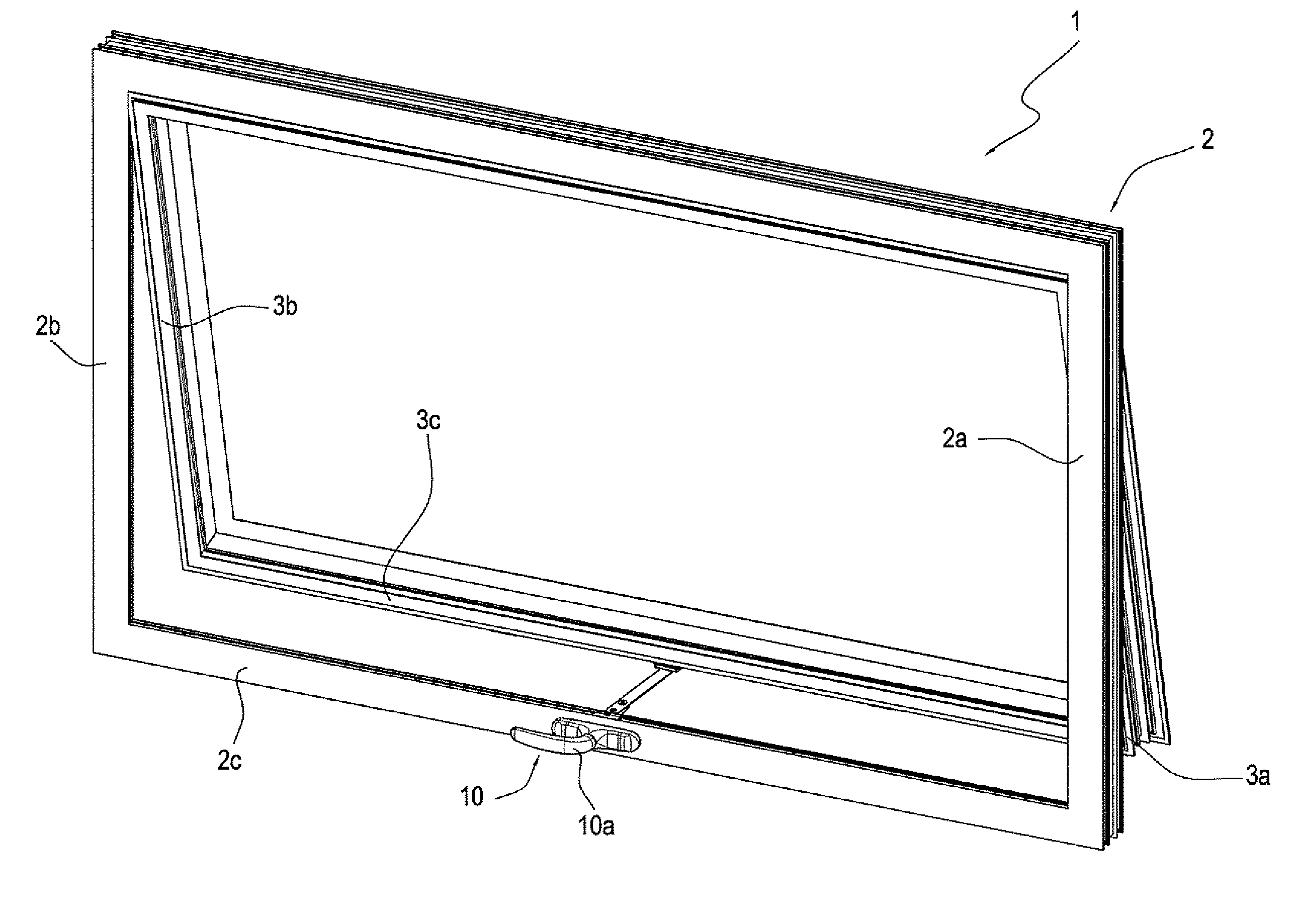
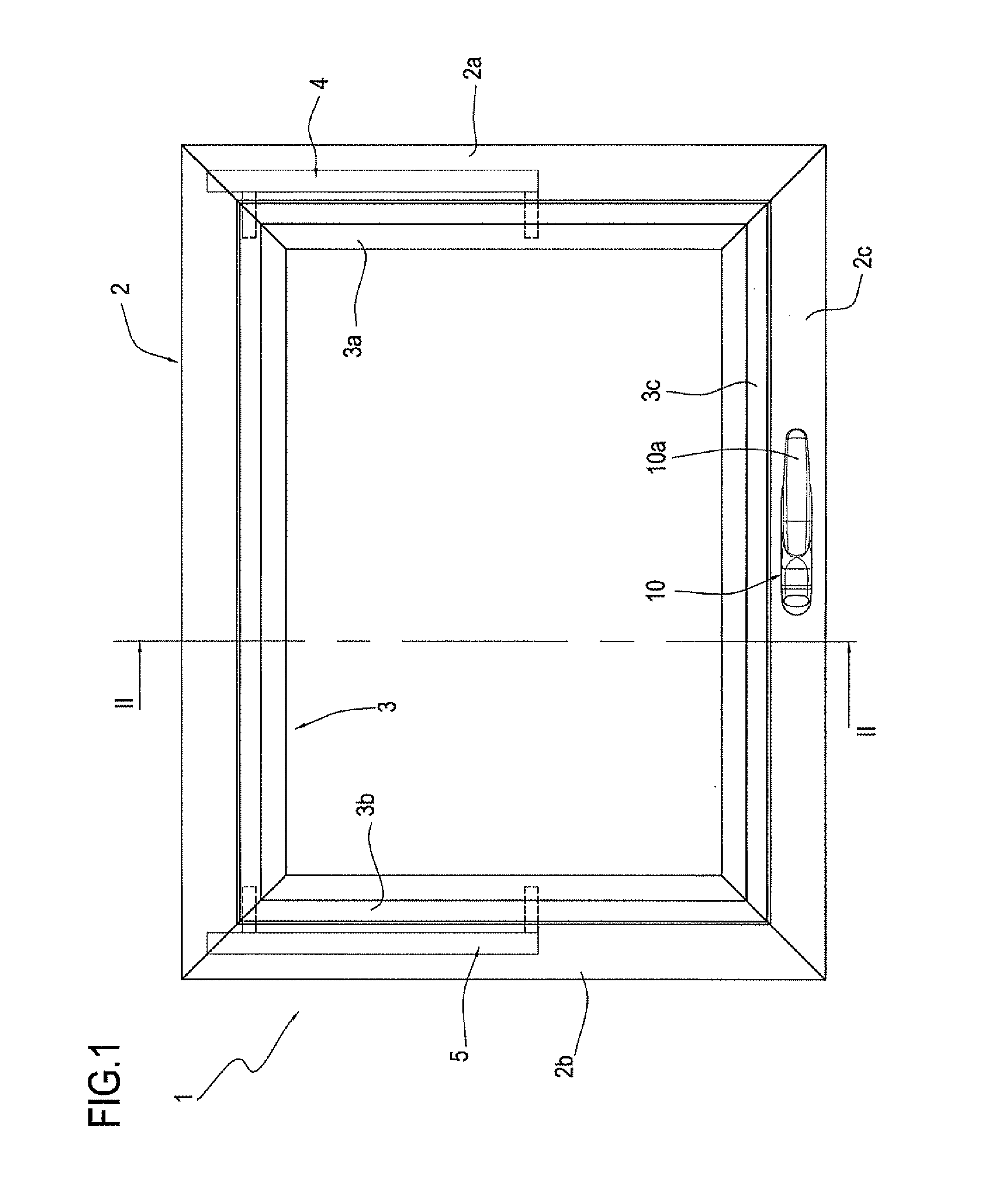
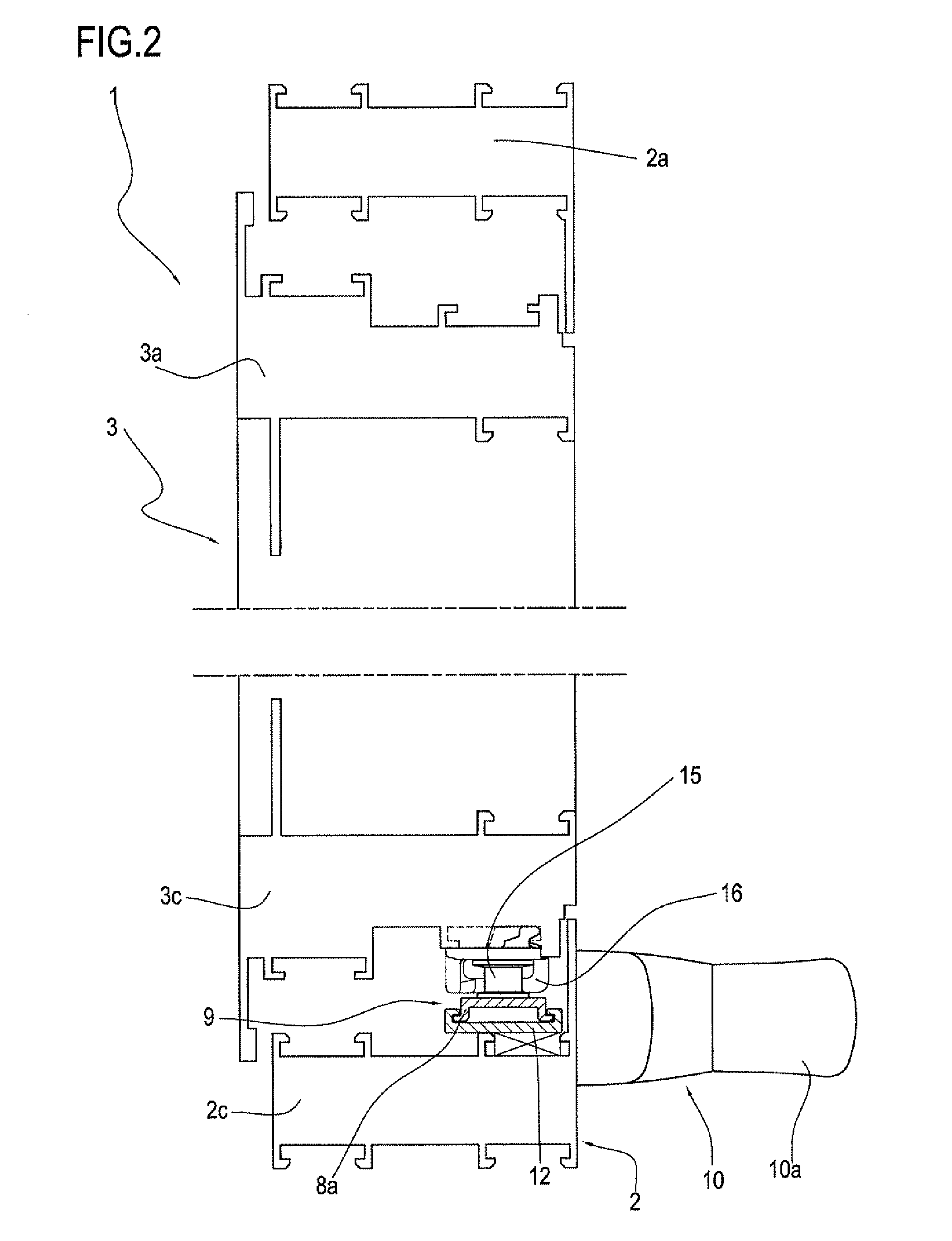
[0047]With reference to the accompanying drawings, and in particular with reference to FIGS. 1 to 3, the window unit according to the invention, denoted by the numeral 1, is of the awning type, that is to say, with a movable frame that opens outwards.

[0048]More specifically, the window unit illustrated is of the type known in the jargon of the trade as “top-hung”, to which this description will expressly refer without limiting the scope of the invention, which can also be applied to awning windows (where the movable frame opens outwards with its lower rail) with traditional hinges, that is, where the movable frame turns about only one horizontal axis

[0049]This window unit 1 basically comprises: a fixed frame 2, a movable frame 3, a pair of hinged members 4, 5, an operating unit 6 comprising several members (described in more detail below) and closing elements 8.

[0050]The fixed frame 2 has a pair of vertical members or stiles 2a and 2b, parallel with each other, and a pair of horizon...


PUM


Abstract

An awning window unit which includes a fixed frame (2); a movable frame (3) connected to the fixed frame by a pair of hinged members (4, 5) joined to respective members of the fixed frame and of the movable frame so as to allow the movable frame to move between a closed position, where the fixed and movable frames are in contact with each other, and an open position, where at least one lower rail (3c) of the movable frame is at a certain distance from the fixed frame towards the outside of the room where the window unit (1) is installed, and vice versa; and a movement arm (7) configured to move the movable frame from the closed position to the open position, and vice versa.

Description

TECHNICAL FIELD[0001]This invention relates to an awning window unit, where the movable frame opens outwards with its bottom rail.BACKGROUND ART[0002]The window of the invention may be included in window configurations with traditional awning opening style, that is to say, windows that rotate about a horizontal axis on traditional hinges, or in the field of traditional awning windows known in the jargon of the trade as “top hung” windows.[0003]Hereinafter, this specification will describe prior art solutions derived from the top hung window but without limiting the scope of the invention to top-hung windows with traditional awning opening style, that is to say, with hinges configured to make the movable frame rotate outwards about a horizontal axis with its bottom rail.[0004]Awning window units, usually made of metal, PVC or the like and of wood, are used for airing rooms and the parts of the windows inside the rooms are often equipped with accessories such as fly screens. In additi...

Claims


Application Information

Patent Timeline
IPC IPC(8): E05F11/10E05C17/50
CPCE05F11/16E05F11/10
Inventor LAMBERTINI, MARCO
Owner GSG INT
Why Eureka
Eureka Blog
Learn More