System and method for controlling combustor operating conditions based on flame detection

a technology of flame detection and operating conditions, applied in the field of gas turbines, can solve the problems of reducing the efficiency of the combustor, reducing the life of the components within the combustor, and damage to the turbine's components

Inactive Publication Date: 2012-07-12
GENERAL ELECTRIC CO
View PDF15 Cites 28 Cited by
  • Summary
  • Abstract
  • Description
  • Claims
  • Application Information

AI Technical Summary

Problems solved by technology

During the operation of a gas turbine, anomalies may occur within the turbine's combustors that increase emissions of regulated combustion products, reduce combustor efficiency and/or reduce the part life of components within the combustor.
For example, excessive flame temperatures within the combustor may cause over-firing conditions, thereby resulting in damage to the turbine's components.
Additionally, excessive flame temperatures can lead to increased emissions and may necessitate increased cooling flow to the combustor, thereby reducing combustor efficiency.
Similarly, lean blow-out (LBO) events, characterized by extinguished flames due to an air/fuel mixture that i

Method used


Image

  • System and method for controlling combustor operating conditions based on flame detection
  • System and method for controlling combustor operating conditions based on flame detection
  • System and method for controlling combustor operating conditions based on flame detection

Examples


Embodiment Construction

[0016]Reference now will be made in detail to embodiments of the invention, one or more examples of which are illustrated in the drawings. Each example is provided by way of explanation of the invention, not limitation of the invention. In fact, it will be apparent to those skilled in the art that various modifications and variations can be made in the present invention without departing from the scope or spirit of the invention. For instance, features illustrated or described as part of one embodiment can be used with another embodiment to yield a still further embodiment. Thus, it is intended that the present invention covers such modifications and variations as come within the scope of the appended claims and their equivalents.

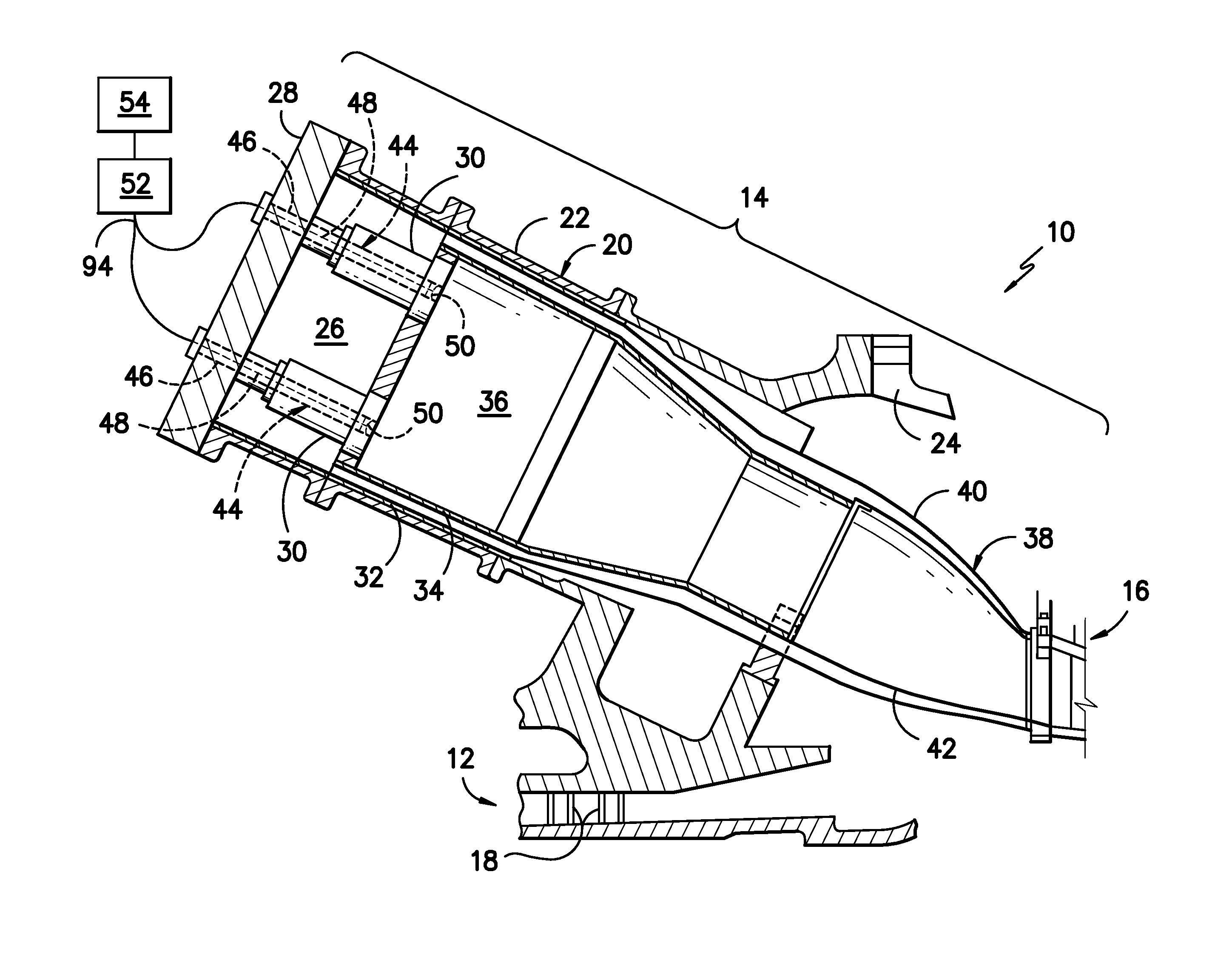
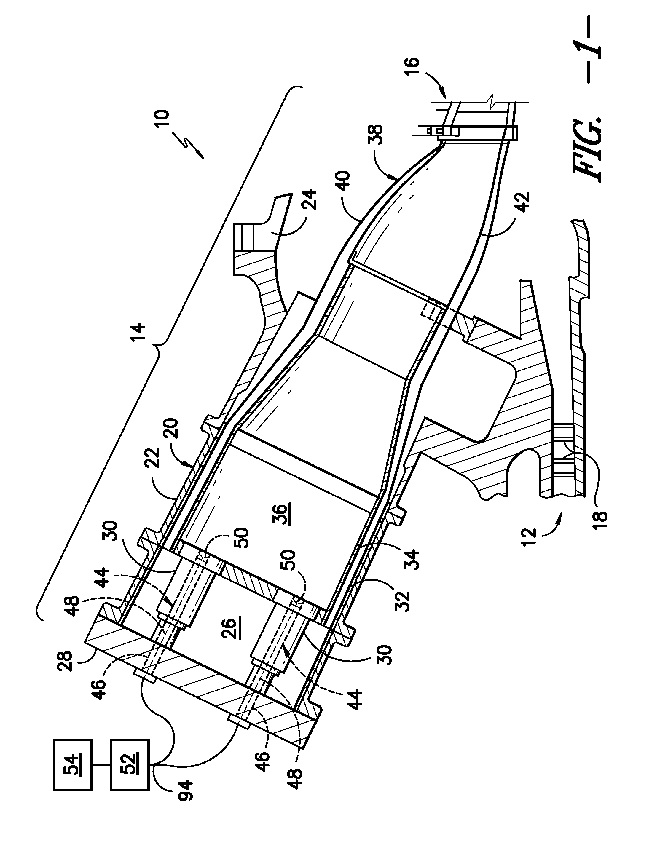
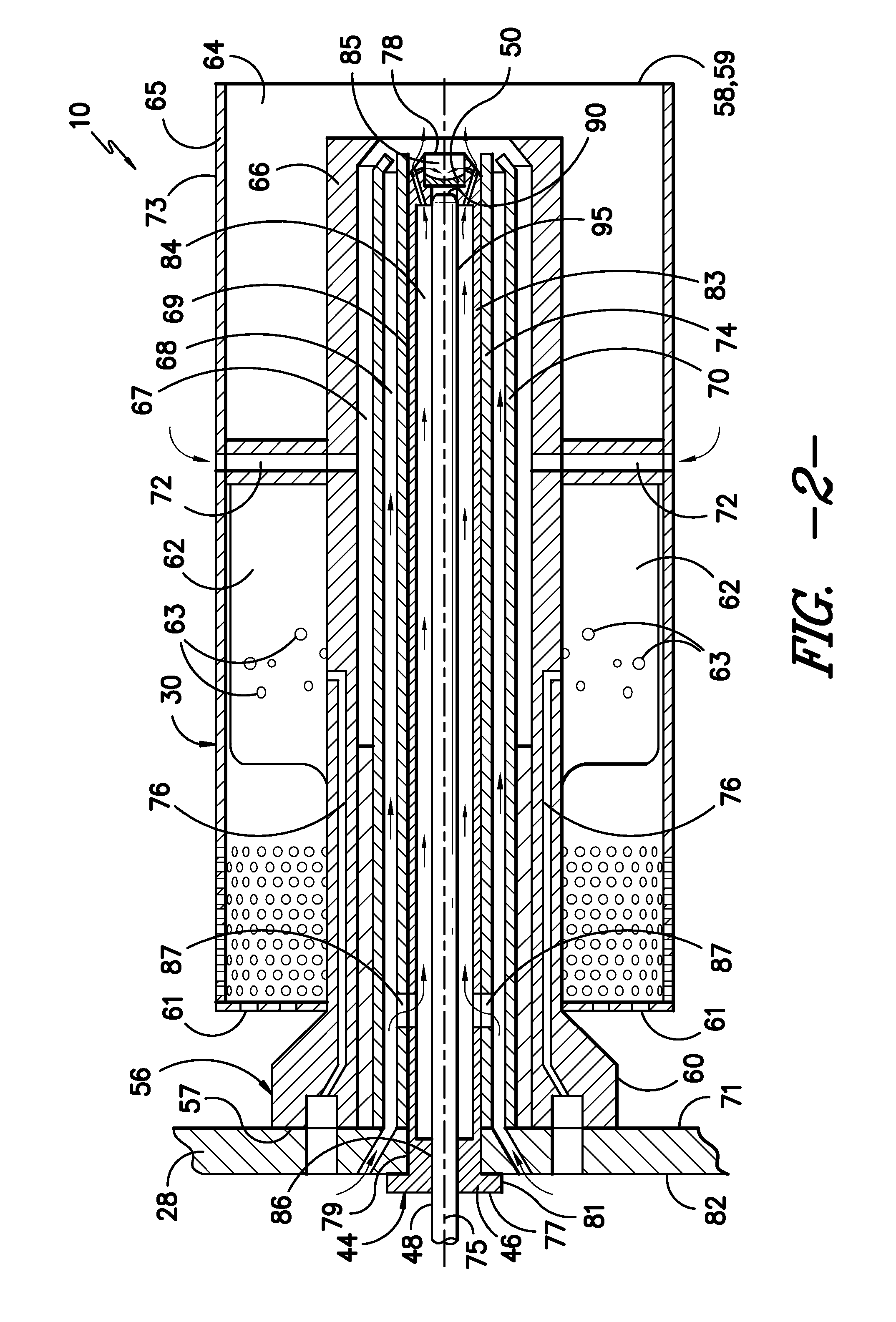
[0017]In general, the present subject matter is directed to a system and method for controlling operating conditions of a gas turbine combustor based on the detection of light from the combustor's flames. The disclosed system generally includes a sensor ass...


PUM

PropertyMeasurementUnit
Flow rateaaaaaaaaaa
Lightaaaaaaaaaa
Flame temperatureaaaaaaaaaa

Abstract

A system is disclosed that includes a combustor having an end cover and at least one fuel nozzle assembly extending from an inner face of the end cover. A cartridge may extend through the end cover and into the fuel nozzle assembly. The cartridge may define an opening for receiving light emitted from within the combustor. Additionally, a fiber optic cable may be disposed within the cartridge and may be configured to capture at least a portion of the light received through the opening.

Description

FIELD OF THE INVENTION[0001]The present subject matter relates generally to gas turbines and, more particularly, to a system and method for controlling operating conditions of a gas turbine combustor based on the detection of light from the combustor's flames.BACKGROUND OF THE INVENTION[0002]Gas turbines typically include a compressor section, a combustion section, and a turbine section. The compressor section pressurizes air flowing into the gas turbine. The pressurized air discharged from the compressor section flows into the combustion section, which is generally characterized by a plurality of combustors disposed around an annular array about the axis of the engine. Air entering each combustor is mixed with fuel and combusted. Hot gases of combustion flow from each combustor to the turbine section of the gas turbine to drive the turbine and generate power.[0003]During the operation of a gas turbine, anomalies may occur within the turbine's combustors that increase emissions of r...

Claims


Application Information

Patent Timeline
IPC IPC(8): F02C1/00G01M15/14G01N21/59F02C7/22B23P17/00
CPCF23N5/082F23N2900/05005F23R3/286G01J5/0018Y10T29/49229G01J5/061G01J5/0806G01J5/0821G01N21/72G01J5/0088
Inventor KRULL, ANTHONY WAYNEZONG, NANKALITAN, DANIELLE MARIE
Owner GENERAL ELECTRIC CO
Why Eureka
Try Eureka