LED Light Tube

Inactive Publication Date: 2012-07-12
LEXTAR ELECTRONICS CORP
View PDF6 Cites 11 Cited by
  • Summary
  • Abstract
  • Description
  • Claims
  • Application Information

AI Technical Summary

Benefits of technology

[0007]Hence, an aspect of the present invention is to an LED light tube which provides

Problems solved by technology

Although the LED light tube has inherited the advantages of the LED for illumination, yet if the LED is simply disposed into a common

Method used


Image

  • LED Light Tube
  • LED Light Tube
  • LED Light Tube

Examples


Example

[0016]In the following detailed description, for purposes of explanation, numerous specific details are set forth in order to provide a thorough understanding of the disclosed embodiments. It will be apparent, however, that one or more embodiments may be practiced without these specific details. In other instances, well-known structures and devices are schematically depicted in order to simplify the drawings.

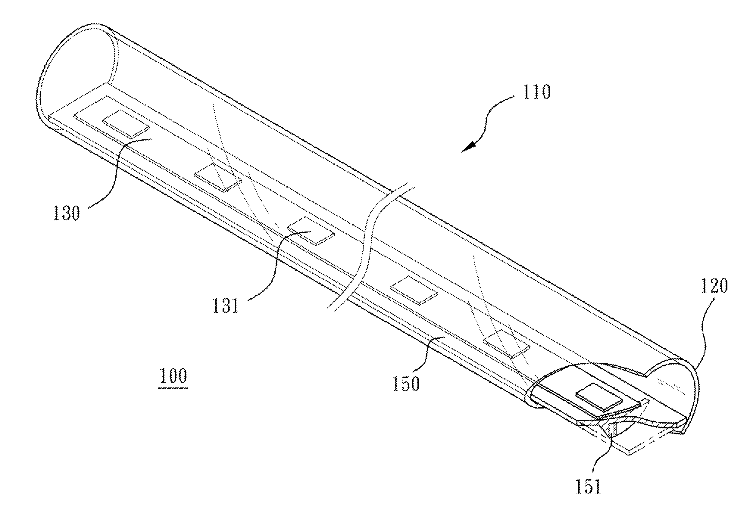
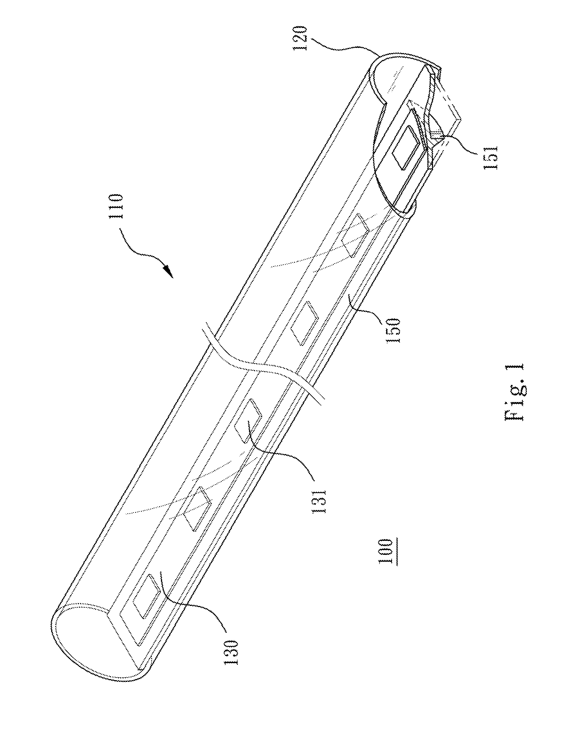
[0017]Referring to FIG. 1, FIG. 1 is a schematic diagram showing the structure of an LED light tube according to one embodiment of the present invention. As shown in FIG. 1, the LED light tube 100 includes a transparent tube 110, a phosphor layer 120 and a base board 130. The phosphor layer 120 is coated on a surface of the transparent tube 110, wherein a thickness of the phosphor layer 120 is 10-100 μm. The base board 130 is arranged inside the transparent tube 110 for carrying a plurality of LEDs 131. The LED light tube 100 provides a lighting system; for example, the LEDs 131...


PUM


Abstract

An LED (Light-Emitting Diode) light tube includes a transparent tube, a phosphor layer and a base board. The phosphor layer is coated on a surface of the transparent tube, wherein a thickness of the phosphor layer is 10-100 μm. The base board is arranged inside the transparent tube for carrying a plurality of LEDs (Light-Emitting Diodes), wherein the length between the base board and the top of the transparent tube is H, and the distance between every two adjacent LEDs is P, and H/P is not smaller than 0.134 and H is 9.5-38 mm.

Description

RELATED APPLICATIONS[0001]The application claims priority to Taiwan Application Serial Number 100100691, filed Jan. 7, 2011, which is herein incorporated by reference.BACKGROUND[0002]1. Technical Field[0003]The present disclosure relates to a light tube. More particularly, the present disclosure relates to an LED (Light-Emitting Diode) light tube.[0004]2. Description of Related Art[0005]An LED is a semiconductor element. In the beginning, the LED is often used as an indicator, a bulletin board and so on; with the appearance of a white LED, the LED is also used for illumination. The LED is a new type of light source in the 21St century, which has the advantages of high efficiency, long operation life, unbreakability with which the other traditional light sources cannot compete. While a forward voltage is applied, the LED can emit a monochromatic and discontinuous light, which is an electroluminescent effect. By changing the chemical compositions of the semiconductor materials forming...

Claims


Application Information

Patent Timeline
IPC IPC(8): F21V9/16F21V9/40
CPCF21K9/17F21Y2103/003F21Y2101/02F21K9/56F21K9/27F21K9/64F21Y2103/10F21Y2115/10
Inventor WU, KUN-HUALIN, CHIH-HAOCHEN, PO-CHANGHUNG, CHENG-WEILIN, YAN-LIANGCHUANG, CHI-HUANG
Owner LEXTAR ELECTRONICS CORP
Why Eureka
Try Eureka