Method and System for Implementing Emergency Location

a technology of emergency location and system, applied in the field of emergency location, can solve the problems of ensuring the ue has the supl, the short message gateway and the wap gateway cannot provide services for the ue, and the sip protocol is too complicated for the slp to suppor

Inactive Publication Date: 2012-07-12
ZTE CORP
View PDF4 Cites 28 Cited by
  • Summary
  • Abstract
  • Description
  • Claims
  • Application Information

AI Technical Summary

Benefits of technology

[0058]It can be seen from the technical scheme provided by the present invention that the UE initiates the SUPL position procedure to the SLP while initiating the emergency call; the SLP obtains the location information of the UE through the SUPL position procedure, and provides the location information of the UE to the LRF. Through the method in accordance with the present invention, the SUPL position procedure is initiated by the UE initiating the emergency call and the SLP is not required to support the SLP protocol, thereby simplifying the design of the SLP. In addition, it is clear to the UE that the UE is a qualified SET, so the location request initiated by the UE can certainly be responded correctly, thereby ensuring successful implementation of the emergency call process.

Problems solved by technology

1) When the UE has no effective International Mobile Subscriber Identifier (IMSI) or card, if the SUPL initiation process shown in FIG. 4 is used, the short message gateway and WAP gateway cannot provide services for the UE.
It is too complicated for the SLP to support the SIP protocol for a simple SIP Message.
3) When the SLP initiates a SUPL INIT message to the UE, it does not ensure that the UE has the SUPL capability, i.e., it does not ensure that the UE is a qualified SET terminal.
Thus, it is possible that the correct response to the SUPL INIT message sent by the SLP can not be obtained, resulting in failure or delay of the emergency call process.

Method used


Image

  • Method and System for Implementing Emergency Location
  • Method and System for Implementing Emergency Location
  • Method and System for Implementing Emergency Location

Examples


Embodiment Construction

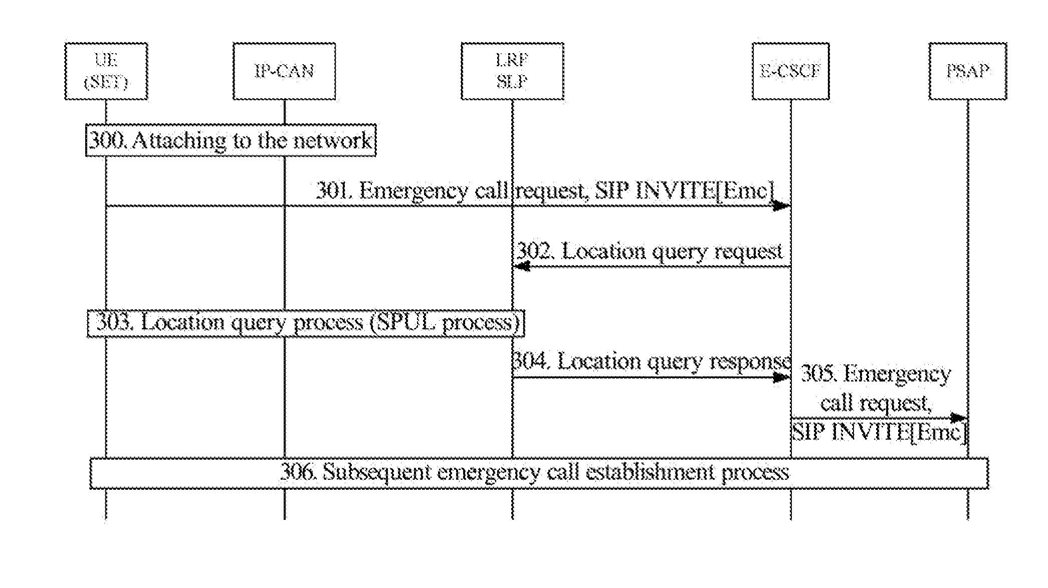
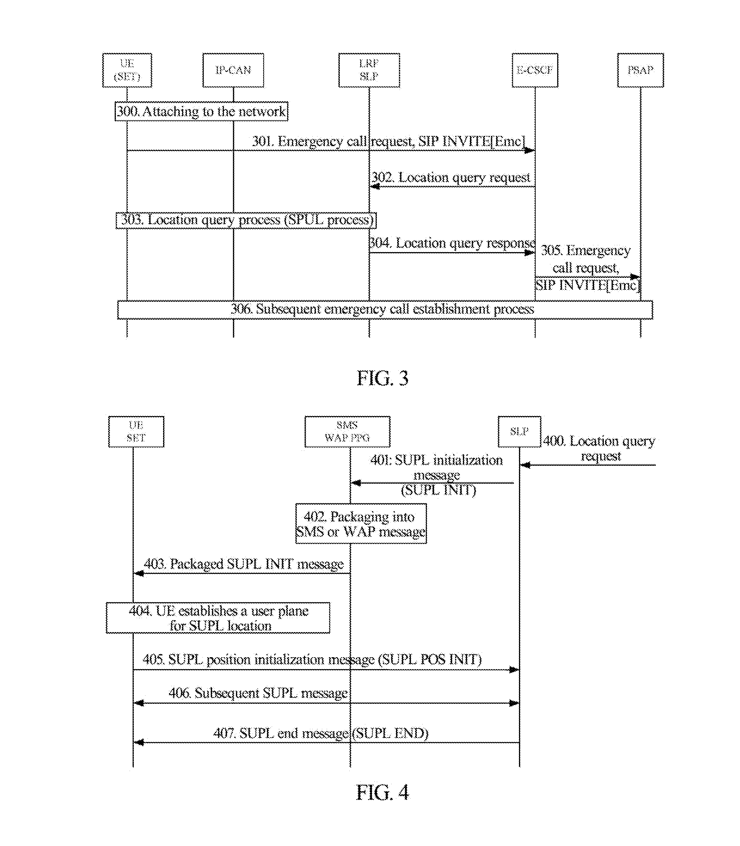
[0068]FIG. 6 is a flowchart of a method for implementing emergency location in accordance with the present invention. As shown in FIG. 6, the method comprises the following steps.

[0069]In step 600, a UE initiates an emergency call, and initiates a SUPL position procedure to a SLP.

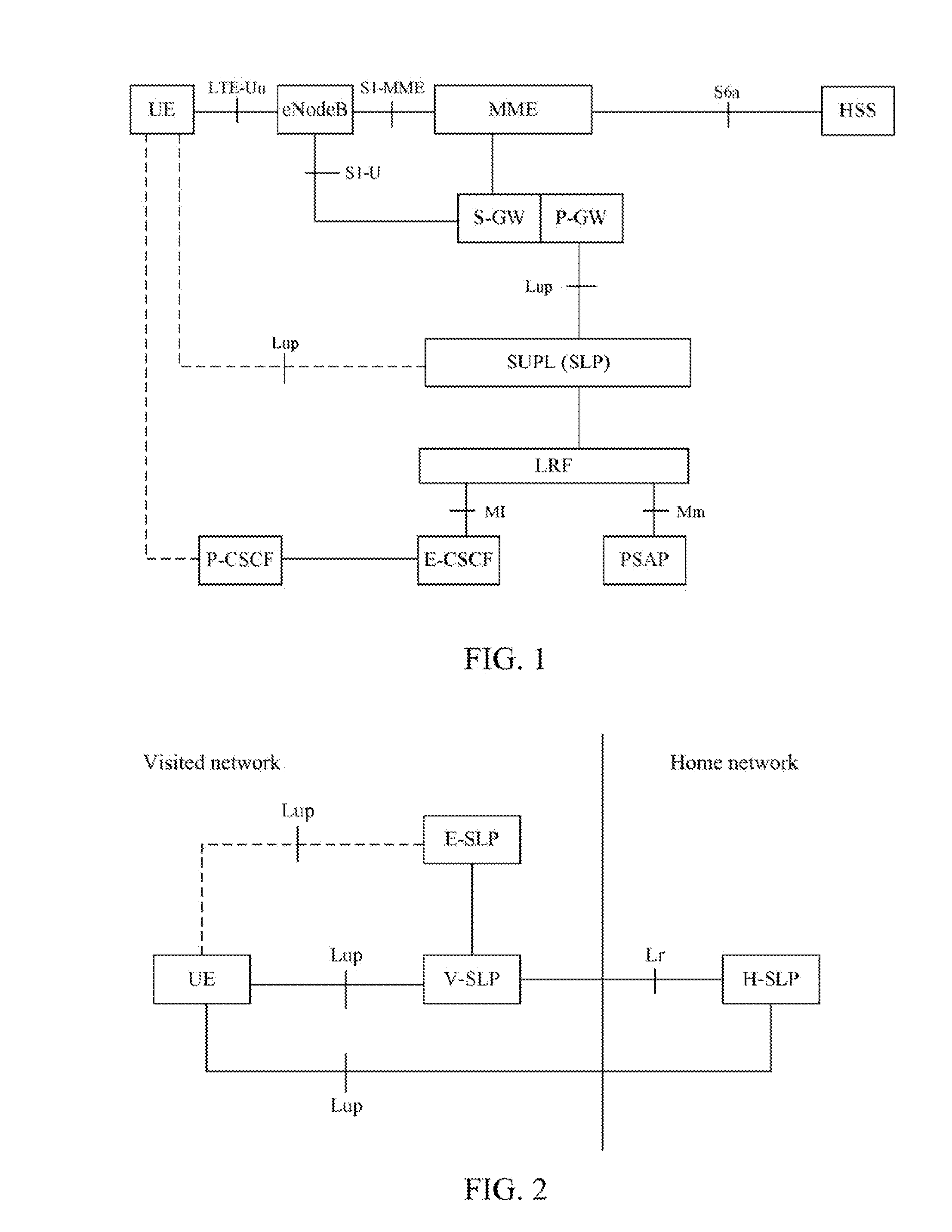
[0070]The UE initiates an emergency call request, i.e., initiates a SIP invite message carrying an emergency identifier, and the emergency call request is routed to an E-CSCF; meanwhile, the UE sends a SUPL initialization message to the SLP, i.e., sends a SUPL start message carrying the emergency identifier to the SLP to initiate the SUPL position procedure. Before attempting the emergency call request, usually an appropriate IP connection for emergency usage shall be established by the UE.

[0071]It should be noted that the UE can immediately initiate a location start request to the SLP after initiating an emergency call request (SIP INVITE) to an IMS;

[0072]Or the UE can firstly initiate the location start r...


PUM


Abstract

The present invention provides a method and system for implementing emergency location. The method comprises: a User Equipment (UE) initiating an emergency call, and initiating a SUPL position procedure to a security user plane location platform (SLP); and the SLP obtaining location information of the UE through the SUPL position procedure, and providing the location information of the UE to a location request function (LRF). Using the method, the SUPL position procedure is initiated by the UE when the emergency call is initiated and the SLP is not required to support the Session Initiation Protocol (SIP), thereby simplifying design of the SLP. Furthermore, it is clear to the UE that the UE is a qualified SET, so the location request initiated by the UE can certainly be responded correctly, thereby ensuring successful implementation of the emergency call process.

Description

TECHNICAL FIELD[0001]The present invention relates to an emergency call technology, and more particularly, to a method and system for implementing emergency location when a User Equipment (UE) having Security User Plane Location (SUPL) ability initiates an emergency call.BACKGROUND OF THE RELATED ART[0002]IP Multimedia Core Network Subsystem (IMS), which is a core of the new generation communication network, uses a Session Initiation Protocol (SIP) system. The SIP stipulates that communication is independent of access, and has abilities of separating multimedia service control function and bearer function, separating call and session, separating application and service, separating service and network, and merging mobile network service and internet network service, etc.[0003]Because the IMS is independent of access, emergency calls under the IMS can be established in the General Packet Radio Service (GPRS) network and System Architecture Evolution (SAE) network to provide the unifie...

Claims


Application Information

Patent Timeline
Patent Type & Authority Applications(United States)
IPC IPC(8): H04W4/22H04W24/00H04W4/20H04W4/02H04W4/90
CPCH04W4/02H04W76/007H04W4/22H04W4/20H04W76/50H04W4/90
Inventor LI, ZHIJUNLI, HUI
Owner ZTE CORP
Why Eureka
Try Eureka