
Controller for Machine Tool

a technology for controlling machines and machines, applied in the field of controllers for machine tools, can solve the problems of reducing the accuracy of workpiece machining, changing into wrong or inappropriate values, wrong codes, etc., and achieve the effect of working parts with safety and not reducing the accuracy of machining

Active Publication Date: 2012-07-12
DMG MORI CO LTD
View PDF9 Cites 24 Cited by
  • Summary
  • Abstract
  • Description
  • Claims
  • Application Information

AI Technical Summary

Benefits of technology

[0005]However, in the above conventional controller, for example, there is a fear that, when a command value, a parameter or a code is changed, it is changed into a wrong or inappropriate value or a wrong code because of an error in changing. If an NC program including a wrong or inappropriate value or a wrong code is executed, there occur a problem that a tool interferes with a workpiece or a machine tool structure and a problem that the accuracy of workpiece machining is reduced.
[0006]According to the foregoing, a controller for a machine tool is capable of, when an NC program including a changed command value, parameter, or code is executed, machining a workpiece with safety without reducing machining accuracy.
[0019]Thus, according to the controller of the present disclosure, since, in a case where an NC program or a parameter was changed, the operation of the feed mechanism is temporarily stopped before or after the operation command of the block immediately preceding a block relating to the changed portion is executed, it is possible to prompt the operator to check the changed portion. Thereby, even if a command value, a parameter or a code is changed to a wrong or inappropriate value or a wrong code because of an error in changing, it is possible to cause the operator to note that. Therefore, it is possible to prevent the occurrence of a problem that the tool interferes with the workpiece or a machine tool structure and a problem that the accuracy of workpiece machining is reduced.
[0023]Thus, a block which does not relate to a cutting command is set as a stop block. Therefore, it is possible to prevent the relative movement of the tool and the workpiece from being temporarily stopped during cutting, and therefore it can be avoided that the accuracy of workpiece machining is reduced by stop of the movement of the tool and the workpiece during cutting.
[0030]As described above, according to the controller of the present disclosure, since, when an NC program or a parameter is changed, the operation of the feed mechanism is temporarily stopped immediately before a block relating to the changed portion, thereby causing the operator to take care, it is possible to machine a workpiece with safety without reducing the machining accuracy.

Problems solved by technology

However, in the above conventional controller, for example, there is a fear that, when a command value, a parameter or a code is changed, it is changed into a wrong or inappropriate value or a wrong code because of an error in changing.
If an NC program including a wrong or inappropriate value or a wrong code is executed, there occur a problem that a tool interferes with a workpiece or a machine tool structure and a problem that the accuracy of workpiece machining is reduced.

Method used


Image

  • Controller for Machine Tool
  • Controller for Machine Tool
  • Controller for Machine Tool

Examples


Embodiment Construction

[0041]Hereinafter, a specific embodiment of the present disclosure will be described on the basis of the accompanying drawings.

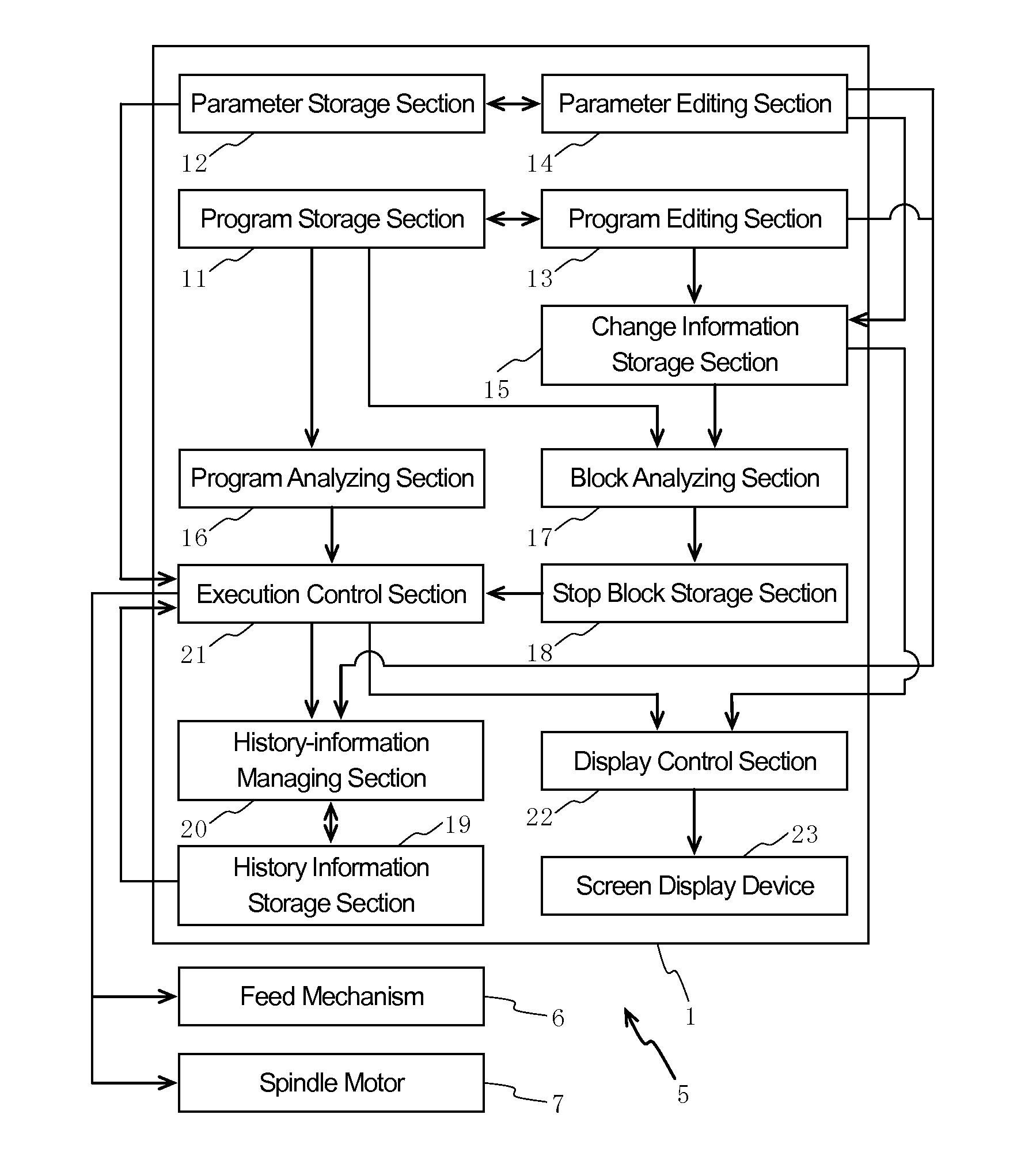
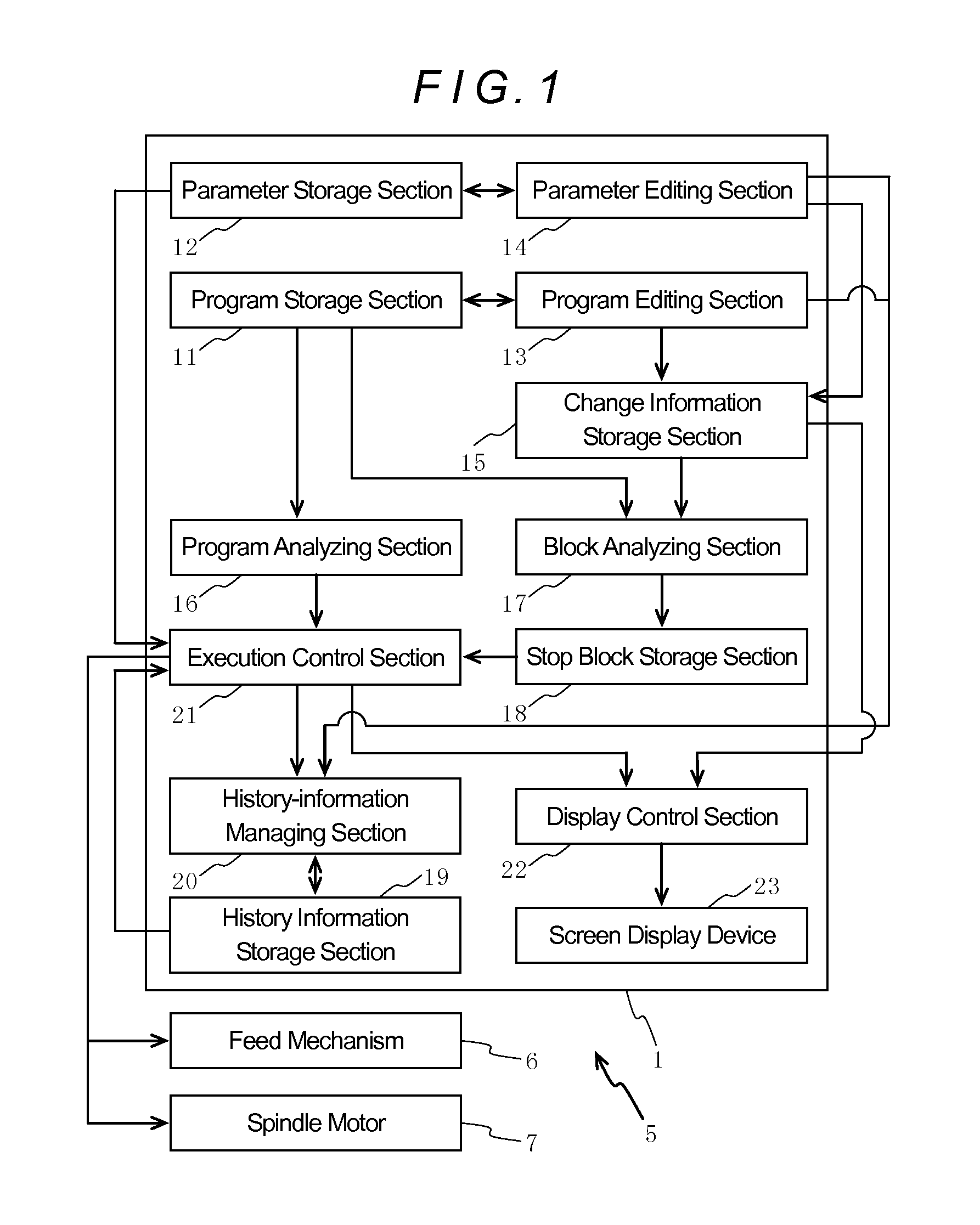
[0042]As shown in FIG. 1, a controller 1 of the embodiment has a program storage section 11, a parameter storage section 12, a program editing section 13, a parameter editing section 14, a change information storage section 15, a program analyzing section 16, a block analyzing section 17, a stop block storage section 18, a history information storage section 19, a history-information managing section 20, an execution control section 21, a display control section 22, a screen display device 23, an input device (not shown) and other components, and is provided on a machine tool 5 configured with a feed mechanism 6 for relatively moving a tool and a workpiece in three orthogonal directions, X-axis, Y-axis and Z-axis directions, and a spindle device for holding the tool or the workpiece and rotating the held tool or workpiece about its axis by means of a spindle...


PUM


Abstract

A controller for a machine tool has a program storage section in which an NC program is stored, a program analyzing section analyzing the NC program block by block in sequence and extracts operation commands for a feed mechanism, an execution control section executing the extracted operation commands and thereby controlling the feed mechanism, e program editing section changing the NC program, and a change information storage section in which change information relating to the changed portion of the NC program is stored. The execution control section, when executing the operation commands, checks whether the block of each operation command is the block immediately preceding a block relating to the changed portion, and when judging that it is the immediately preceding block, temporarily stops the operation of the feed mechanism before or after the execution of the operation command.

Description

TECHNICAL FIELD[0001]The present disclosure relates to a controller for a machine tool for controlling a feed mechanism which relatively moves a tool and a workpiece. More specifically, the present disclosure relates to a controller for a machine tool configured to be capable of editing an NC program and a parameter.BACKGROUND ART[0002]As a controller for a machine tool, conventionally, the controller disclosed in the Japanese Unexamined Patent Application Publication No. 7-227739 is known, for example. This controller has a program storage section in which an NC program is stored, an override switch for changing, when the NC program stored in the program storage section is executed, a feed rate and a rotational speed of spindle which are commanded in the NC program, an override value storage section in which an override value of the override switch is stored, an editing section editing the NC program stored in the program storage section on the basis of the override value stored in...

Claims


Application Information

Patent Timeline
Patent Type & Authority Applications(United States)
IPC IPC(8): G06F19/00
CPCG05B19/4068G05B2219/36073G05B19/4155G05B19/408
Inventor NAKAMURA, TAKAYUKIASADA, TETSUSHISOGA, TAKAAKI
Owner DMG MORI CO LTD
Learn More