Tie strap structure

a technology of tie straps and straps, which is applied in the direction of hose connections, flexible elements, packaging, etc., can solve the problems of inability to reuse tie straps, increase costs, waste of resources, etc., and achieve excellent security in use, convenient use, and cost saving

Inactive Publication Date: 2012-07-19
CHEN KEVIN FONG
View PDF16 Cites 17 Cited by
  • Summary
  • Abstract
  • Description
  • Claims
  • Application Information

AI Technical Summary

Benefits of technology

[0015]A primary object of the present invention is to provide a versatile tie strap structure, which can be conveniently used.
[0016]A further object of the present invention is to provide the above tie strap structure the tightness of which can be adjusted by a user himself/herself as necessary.
[0017]A still further object of the present invention is to provide the above tie strap structure, which can be reused to save cost.
[0018]A still further object of the present invention is to provide the above tie strap structure, which has excellent security in use.
[0019]To achieve the above and other objects, the tie strap structure of the present invention includes a elastic main body and at l

Problems solved by technology

Therefore, the tie strap cannot be reused.
This leads to waste of resource and increase of cost and fails to meet the requirement of environmental protection.
Moreover, the conventional tie strap can be hardly conveniently used.
Furthermore, the tightness of the conventional tie strap cannot be freely adjusted by a user himself/herself.
This may lead to security problem in use of the tie strap.
When doing this, it often takes place that the user negligently cuts his/her own finger.
In some other cases, when a user (such as a child) plays the tie strap, the user may incautiously incorrectly tie up a part of his/her own body with the tie strap, (such as the finger or the neck).
Under such circumstance, a child often fails to immediately loosen the tie strap.
As a result, after a period of time, the tied up part may become necrotic.
In some more serious cases, such situation may lead to death.
However, it is inconvenient to use such tie strap.
After a period of time, the user's finger will feel uncomfortable or painful.
Moreover, since the press end 132 has a quite small press area, it

Method used


Image

  • Tie strap structure
  • Tie strap structure
  • Tie strap structure

Examples


Embodiment Construction

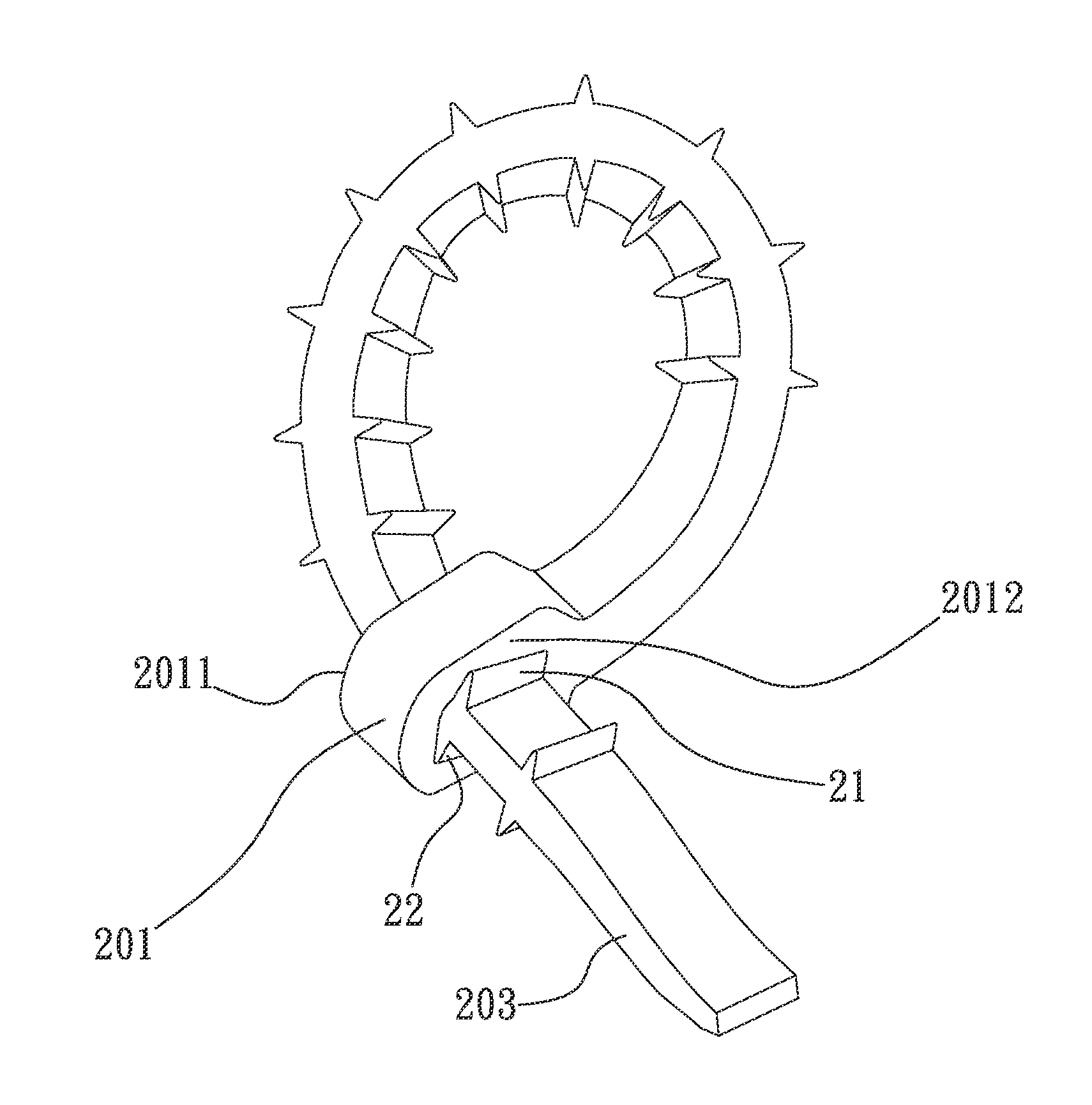
[0029]Please refer to FIGS. 2A and 2B, which show a first embodiment of the tie strap structure of the present invention. The tie strap structure includes at least one first raised section 21, at least one second raised section 22 and a elastic main body 2. The elastic main body 2 has an anchor section 201 and an insertion section 203. The anchor section 201 has a first abutment side 2011, a second abutment side 2012 opposite to the first abutment side 2011 and a through hole 2013. The through hole 2013 has, but not limited to, an elliptic configuration for illustration purposes only. Alternatively, the through hole 2013 can have a rectangular configuration, circular configuration or any other suitable configuration. The through hole 2013 is positioned between the first and second abutment sides 2011, 2012 for the insertion section 203 to correspondingly insert therethrough.

[0030]The anchor section 201 has an elliptic configuration or any other suitable configuration such as a recta...


PUM


Abstract

A tie strap structure includes a elastic main body and at least one first raised section. The elastic main body has an anchor section and an insertion section outward extending from the anchor section. The anchor section has a first abutment side, a second abutment side opposite to the first abutment side and a through hole for the insertion section to correspondingly insert therethrough. The first raised section is formed on one side of the insertion section and projects from the side of the insertion section. It is convenient to use the tie strap structure and the tie strap structure is manufactured at lower cost.

Description

FIELD OF THE INVENTION[0001]The present invention relates to a tie strap structure, and more particularly to a versatile tie strap structure, which can be conveniently reused to save cost.BACKGROUND OF THE INVENTION[0002]The conventional tie straps are widely used in daily life to fix or bundle articles. For example, a tie strap can be used to keep the electrical wires of electrical devices, bundle sundries and so on.[0003]Please refer to FIG. 1A. The conventional tie strap includes an anchor section 10 and a strap body 11. The anchor section 10 is formed with a through hole 101 in which a latch tooth 103 is formed. The strap body 11 is formed with cooperative engagement teeth 112 arranged on the strap body 11 corresponding to the latch tooth 103. In use, the strap body 11 is first wound around the articles to be bundled and then passed through the through hole 101 of the anchor section 10. Then the strap body 11 is pulled tight to latch the engagement teeth 112 of the strap body 11...

Claims


Application Information

Patent Timeline
IPC IPC(8): B65D63/00
CPCY10T24/14B65D63/1018
Inventor CHEN, KEVIN FONG
Owner CHEN KEVIN FONG
Why Eureka
Try Eureka