Conical rotary valve for chromatographic applications

a chromatographic and rotary valve technology, applied in the direction of valve details, plug valves, engine components, etc., can solve the problems of inboard/outboard leakage, cross port leakage, and reduced working behaviour of the valv

Active Publication Date: 2012-07-19
APN INC
View PDF25 Cites 9 Cited by
  • Summary
  • Abstract
  • Description
  • Claims
  • Application Information

AI Technical Summary

Benefits of technology

[0010]Advantageously, it will be appreciated that this arrangement of the radial arms and stoppers ...

Problems solved by technology

As before, this imbalance can increase the sealing force at region 33 and reduce it at region 35, potentially leading to cross port leaks, as well as inboar...

Method used


Image

  • Conical rotary valve for chromatographic applications
  • Conical rotary valve for chromatographic applications
  • Conical rotary valve for chromatographic applications

Examples


Embodiment Construction

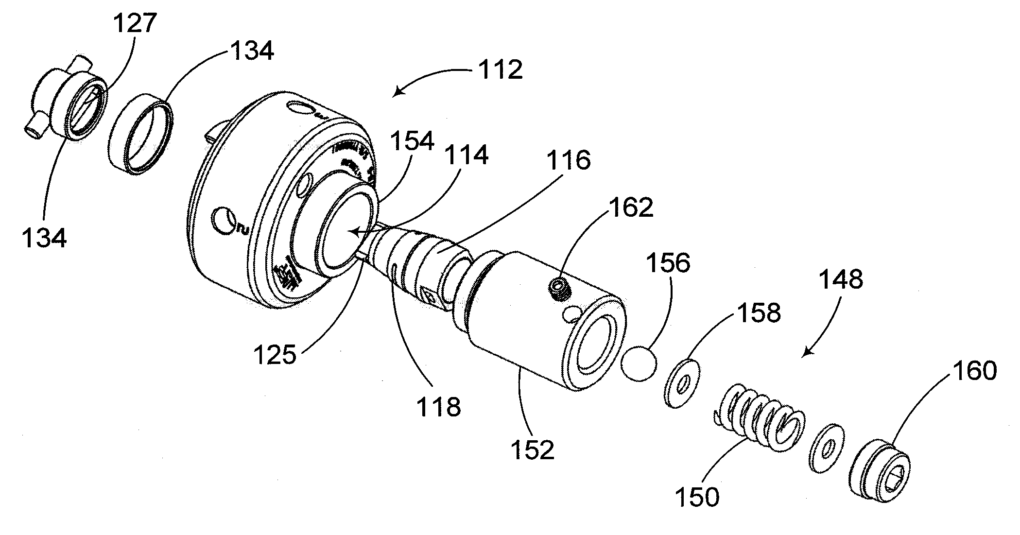
[0033]In accordance with aspects of the present invention, there are provided rotary-type valves for chromatographic applications, designed to prevent or limit leaks.

[0034]Chromatography is understood to refer to laboratory techniques involving the separation of gases or fluids. Valves for use in chromatographic applications therefore provide for the controlled circulation of samples through various paths, as required by the context of the application. For most chromatographic applications, cross-contamination or inboard / outboard leaks are important issues which may have a strong impact on the results obtained from the procedures performed and the life expectancy of the components involved.

[0035]It has been found that an important source of leaks in such valves results from deformations in the rotor due to undesirable forces applied thereto in operation.

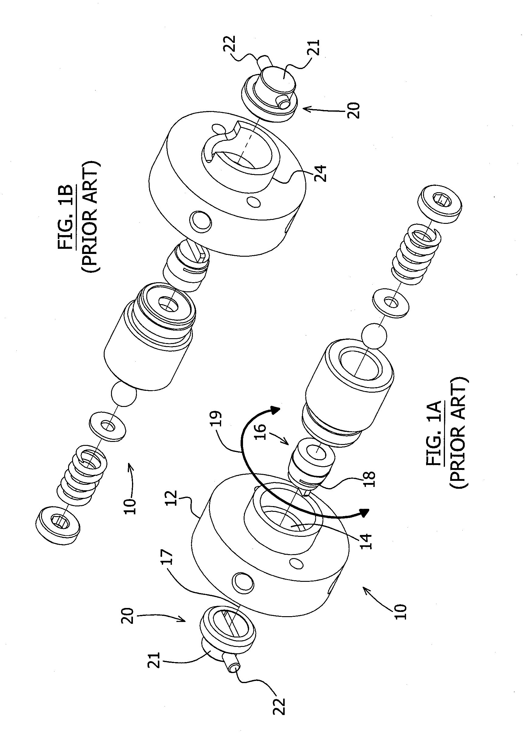
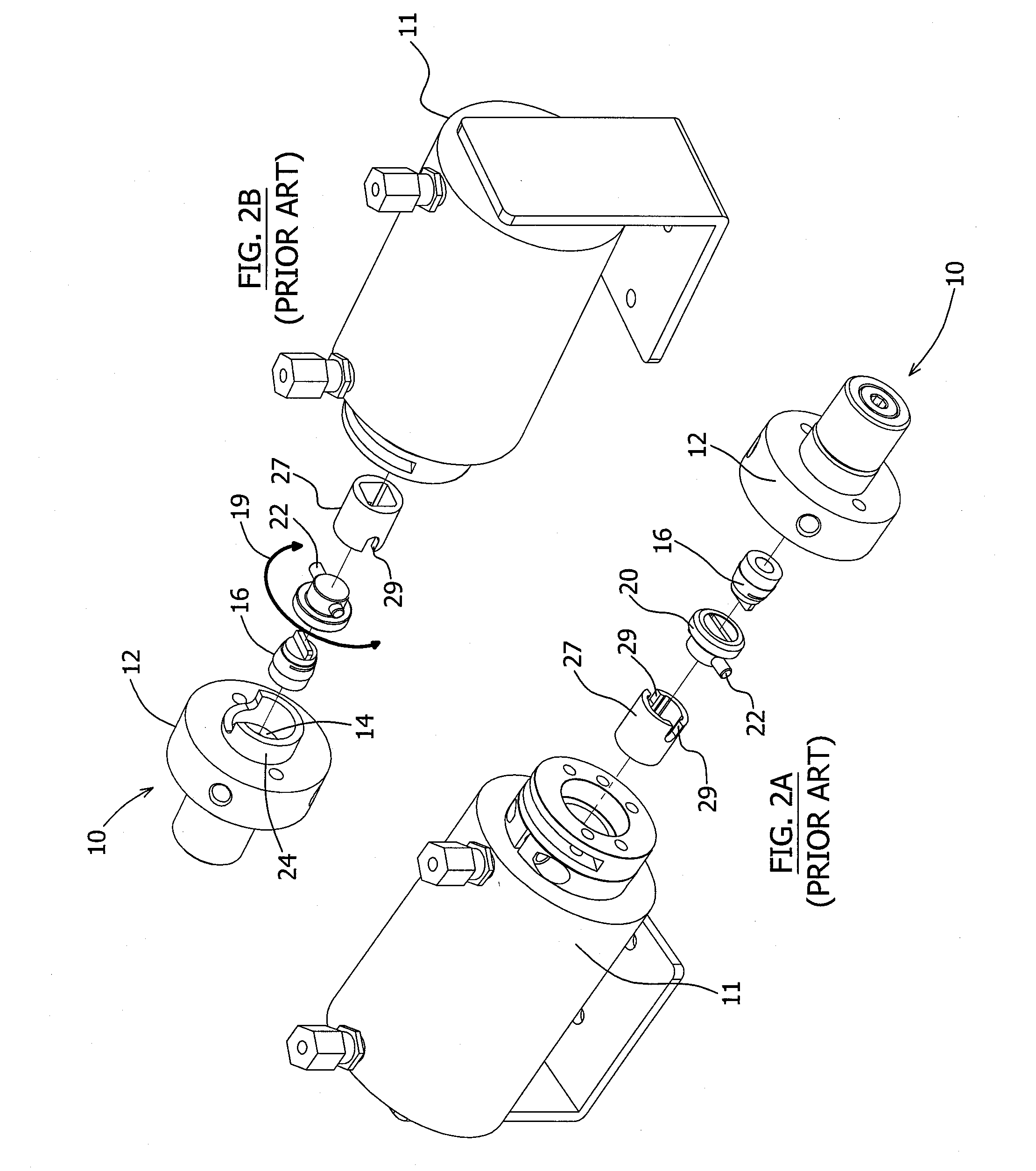
[0036]Referring to FIGS. 4, 4A and 4B for visual support, for conventional rotary valves such as shown in FIGS. 1A and 1B, very oft...


PUM


Abstract

A conical rotary valve for chromatographic applications is provided, including a valve stator, a valve rotor, a drive adaptor and a pair of stoppers each mounted to the stator. The drive adaptor is rotatable and coupled to the valve rotor for transmitting a rotating force thereto. The drive adaptor has a body and a pair of radial arms projecting from the body radially outward from the axis of rotation on opposite sides thereof. Each of the pair of radial arms is movable along a respective arcuate travelling course with respect to the stator. The stoppers are each positioned to obstruct one of the radial arms at an end of the corresponding travelling course. The stoppers are positioned to simultaneously engage the radial arms, thereby balancing the reaction forces created within the valve when the radial arms reach the ends of their travelling courses.

Description

FIELD OF THE INVENTION[0001]The present invention generally relates to rotary valves and more particularly concerns an improved rotary valve for chromatographic applications designed to prevent or limit leaks.BACKGROUND[0002]“Conical”-type rotary valves have been in use for over 40 years in chromatographic applications and various other sampling systems. Early conical valve designs include “plug” or “stopcock” valves, such as for example shown in U.S. Pat. No. 2,830,738 (Sorg et al); U.S. Pat. No. 2,211,627 (Morgan); U.S. Pat. No. 2,972,888 (Lamkin); U.S. Pat. No. 3,116,642 (Weir); U.S. Pat. No. 3,475,950 (Ferrin); U.S. Pat. No. 3,683,701 (Gunther et al); and U.S. Pat. No. 4,133,640 (Clinton et al).[0003]Typically, a rotary valve includes a stator having a plurality of fluid-open ports therein opening on its inner surface, and a rotor coaxially extending within the stator and rotatable with respect to their common axis. The rotor has channels or grooves opening on its outer surface,...

Claims


Application Information

Patent Timeline
IPC IPC(8): F16K31/44F16K5/00
CPCF16K5/0242F16K31/528F16K5/08
Inventor GAMACHE, YVESFORTIER, ANDRE
Owner APN INC
Why Eureka
Try Eureka