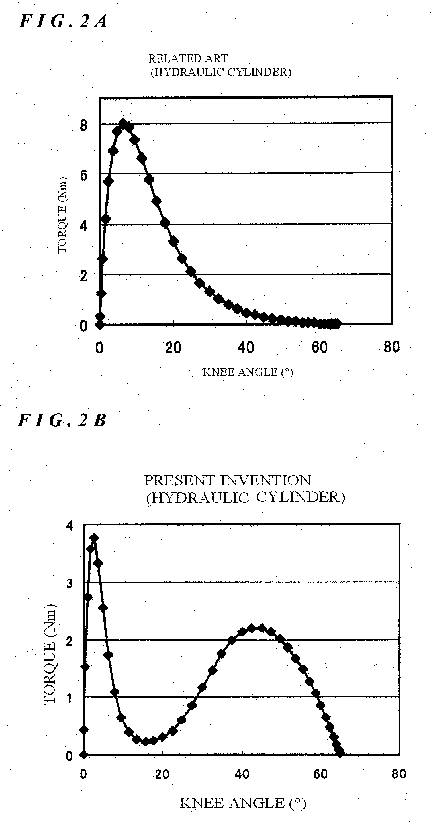
[0019]The first technological significance of the present invention is to provide a novel prosthetic limb which satisfies the relation of T1≦T2. According to the novel prosthetic limb of the present invention, the torque T1 produced at the first stage of initial period of bend of knee joint is relatively small. This torque T1 is small enough even compared with the torque produced by the wearer's weight (see FIG. 4). Accordingly, the load occurrable in the initial period of bend of knee joint is not felt as a burden by the wearer. One example when felt by the wearer as a burden at the time of bend of knee joint according to the present invention can be obtained from the characteristics curve o, shown in a
solid line of FIG. 4. Likewise, one example when felt by the wearer as a burden can be known from the characteristics curve a, shown in a broken line of FIG. 4. The first
advantage of the present invention will become manifest from the comparison between those two characteristics curves o and a, i.e., such a basic
advantage that in
spite of utilizing a hydraulic cylinder or a spring cylinder in the present invention, the load felt by the wearer as a burden in the initial period of bend of knee joint can be reduce to the size when a pneumatic cylinder is utilized. In the final period of bend of knee joint, however, since the torque T2 is relatively increased, the knee is not excessively bent. Accordingly, comfortable walk following properties can be obtained. This is the second
advantage of the present invention.
[0020]The second technological significance of the present invention for providing such a novel prosthetic limb as mentioned above, resides in a method for specifying the arrangement of the drag generating means, such as a hydraulic cylinder or a spring cylinder, more particularly a method for specifying the attachment position of the drag generating means with respect to a multiple-link mechanism that constitutes the knee joint. Since the present invention provides a method for specifying the arrangement of the drag generating means, the constitution of the drag generating means, per se remains same as that of the related art and thus, no complicated constitution is required. A plurality of methods may be employed as a concrete method for specifying the arrangement.
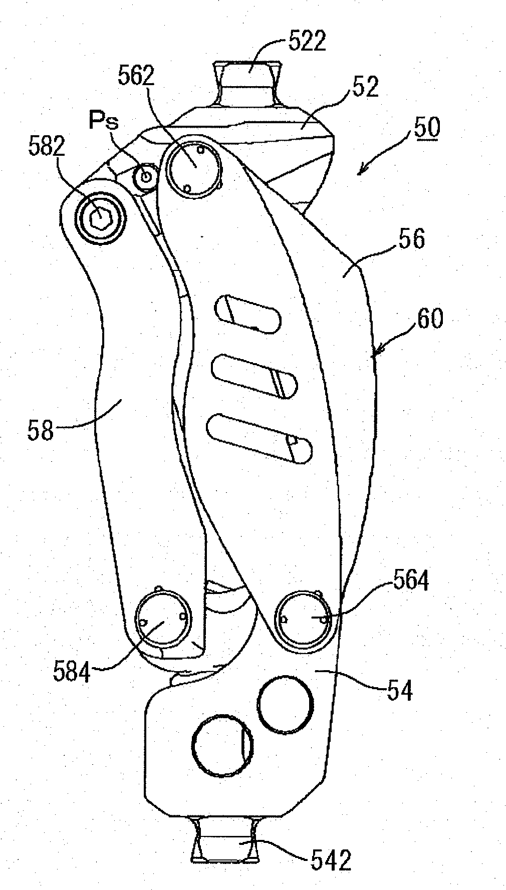
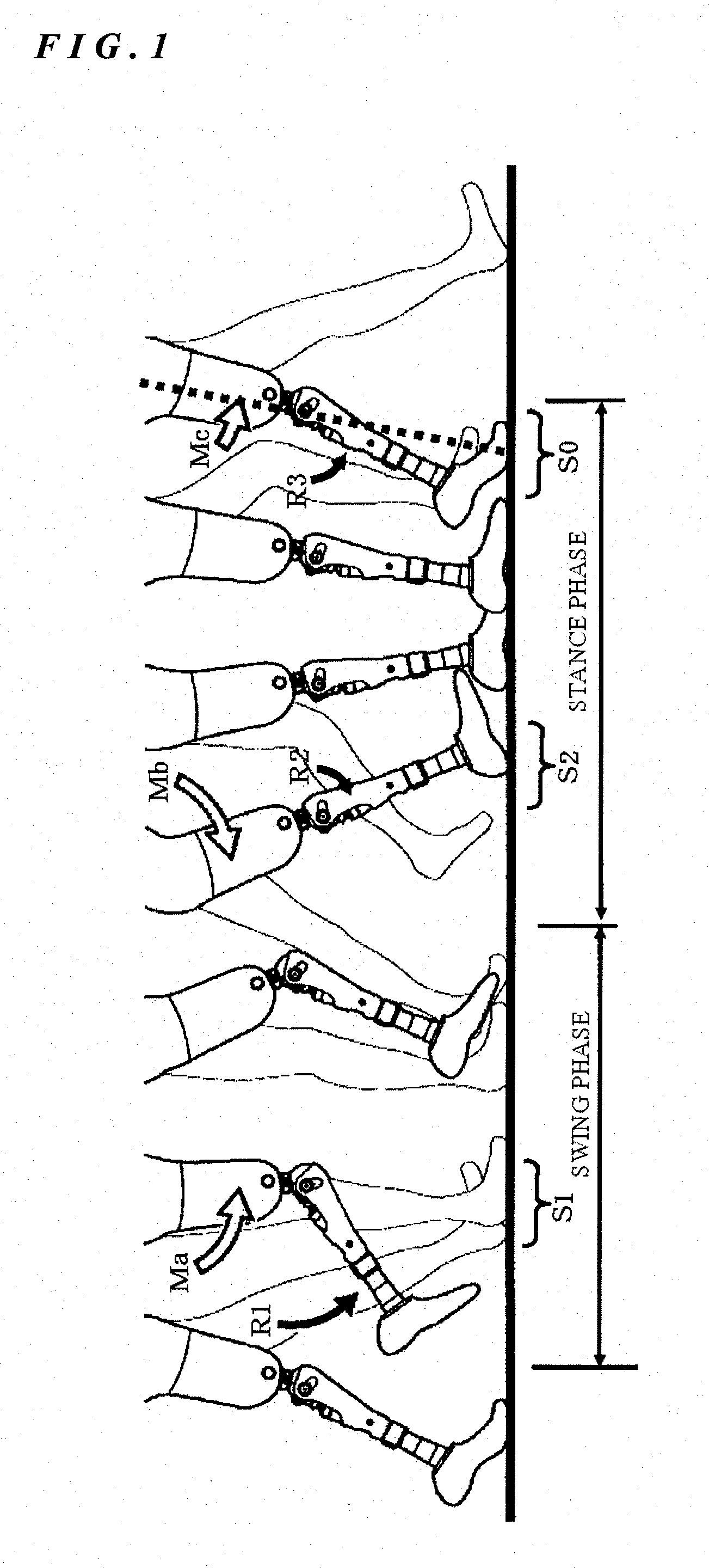
[0021]The first method for specifying the arrangement is achieved by an idea for paying attention to the length L of the lever arm. The length L1 of the lever arm at the first stage of initial period of bend of knee joint is made smaller than the length L2 of the lever arm at the second stage of final period of bend of knee joint. In other words, a relation of L1<L2 is satisfied. It is preferable that the length L of the lever arm at an arbitrary angle in the initial period of bend of knee joint is set to zero (0). By doing so, after this angle, the length L of the lever arm is increased until the walking form is advanced into the final period of bend of knee joint. Thus, a relation of L1<L2 can necessarily be obtained. FIG. 5 diagrammatically shows the first method. In FIG. 5, the four-link mechanism 10 is in a state of the initial period of bend of knee joint wherein the bending angle ,,s is in the range of 0°<,,s<45°. The bending angle ,,s is a knee angle in the initial period of bend of knee joint where the drag is desired to be made small. The bending angle ,,s is normally about 20°, though it is slightly depending on individual wearers of the prosthetic limb. The four-link mechanism 10 comprises four links, namely, a link 12 corresponding to the upper member, a link 14 corresponding to the lower member, a front link 16 and a rear link 18. The drag generating means is attached to the multiple-link mechanism 10 at two spots, e.g., one at a link 12 corresponding to the upper member and the other at a link 14 corresponding to the lower member.
[0022]A straight line 1s is obtained as shown in FIG. 5, which straight line 1s passes through the instantaneous center Os of rotation of the four-link mechanism 10 at the bending angle ,,s and the upper attachment position Ps of the drag generating means. According to the idea of the first method of the present invention, the lower attachment position Qs of the drag generating means is arranged on this straight line 1s. According to the arrangement based on this idea, since the length L of the lever arm at the knee bending angle ,,s is zero (0), the torque is also zero (0) at that time. The upper attachment position Ps of the drag generating means is arranged between the respective connection points 26, 28 which connect the front and rear links 16, 18 with the link 12 corresponding to the upper member, and thus, normally on a member which constitutes the upper member. In contrast, the lower attachment position Qs of the drag generating means is arranged on the straight line Qs and between the respective connection lines 46, 48 which connect the front and rear links 16, 18 with the link 14 corresponding to the lower member, but when the bending angle ,,s is about 20° that is the normal bending angle, the lower attachment position Qs is arranged above the height position which connects the two connection points 46, 48 to each other. In practice, the lower attachment position Qs and the upper attachment position Ps of the drag generating means are arranged on the straight line 1s while avoiding interference with the members which constitute the respective links and other
peripheral parts. What is required for the lower attachment position Qs and the upper attachment position Ps is located on the straight line 1s and so, they may be located above the link 12 corresponding to the upper member or under the link 14 corresponding to the lower member.
[0023]In order to further reduce the burden felt by the prosthetic limb wearer in the initial period of bend of knee joint, it is effective that the bending angle ,,s is made smaller. FIG. 6A shows the characteristics obtainable when the bending angle ,,s is set approximately to 20° that is the normal bending angle. In contrast, FIG. 6B shows the characteristics obtainable when the bending angle ,,s is set to 5°. It will be understood from those Figures that the torque felt by the wearer as a burden, can be reduced by making the bending angle ,,s smaller. However, when the torque is made excessively small in the initial period of bend of knee joint (for example, when the bending angle ,,s is set to 5°), the torque obtainable at the time of extension of knee joint (see FIG. 4) is also small. As a result, it gives rise to such problems that a terminal
impact (namely, the
impact occurrable when the
piston hits the bottom of the cylinder vigorously) that is likely to occur by the torque produced by the drag generating means at the time of extension of knee joint, is difficult to restrain. By employing other known means (for example, a
cushion member provided to the bottom part of the cylinder) for restraining the terminal
impact, the bending angle ,,s may be set smaller (for example, 10° or even smaller) than the normal 20°. In order to further simplify the constitution, however, it is desired that by selecting the set value of the bending angle ,,s (preferably a value that is larger than 10° but smaller than 20°), the terminal impact caused by the torque produced by the drag generating means at the time of extension of knee joint is restrained. It should be noted that when the bending angle ,,s at which the length L of the lever arm is desired to make zero (0) is made small, the lower attachment position Qs of the drag generating means is further lowered in height position and thus,
much difficulty is encountered for the drag generating means to avoid interference with other parts.
[0024]According to the first method of the present invention, the length of the lever arm in the initial period of bend of knee joint where the drag is desired to be made small is set to zero (0), thereby reducing the torque produced by the drag generating means. According to the second method of the present invention, attention is also paid to the
moving speed of the
piston of the drag generating means while employing the entire constitution of the first arrangement method. FIG. 7 diagrammatically shows the second method of the present invention. According to the second method, the lower attachment position Qs of the drag generating means is arranged on the straight line 1s at the time when the bending angle ,,s is, for example, about 20°. This procedure is same as in the first method. In addition to that, according to the second method of the present invention, the lower attachment position Qs is more strictly specified to a particular point Qi. A smaller bending angle ,,o (for example, 0°) than the bending angle ,,s is selected and the upper attachment position of the drag generating means at that time is represented by Po. According to the second method, the particular point Qi located on the straight line 1s and
equidistant from the upper attachment position Ps at the larger bending angle ,,s and the upper attachment position Po at the smaller bending angle ,,o is determined as the lower attachment position of the drag generating means. By specifying the lower attachment position in such a manner as just mentioned, the overall length of the drag generating means can be almost fully prevented from being varied at the time when the knee angle is varied from the smaller bending angle ,,o to the larger bending angle ,,s. Accordingly, the drag generating means does not produce the force F during such bending period and the torque that is a resistance, is hardly fluctuated. As the prosthetic limb including the knee joint, a hip
prosthesis is known besides the above
knee prosthesis. In case of the hip
prosthesis, torque caused by the wearer's weight in the initial period of bend of knee joint is more difficult to produce than in the case with the above
knee prosthesis. Accordingly, this second method of the present invention is more advantageously applicable to the hip
prosthesis rather than to the above
knee prosthesis.

