Wind and Updraft Turbine

a wind turbine and turbine technology, applied in the field of wind turbines, can solve the problems of increasing the cost of such fuels, the difference between continuing operation and bankruptcy, and the cost is significant for residential users

Inactive Publication Date: 2009-06-04
BRI ENERGY SOLUTIONS
View PDF9 Cites 18 Cited by
  • Summary
  • Abstract
  • Description
  • Claims
  • Application Information

AI Technical Summary

Benefits of technology

[0010]In one aspect, the current inducing rotor comprises a circular array of permanent magnets, the current generating stator comprises a circular array of wound coils, the circular array of wound coils extends around a circumference of the cylindrical pole and is rigidly attached thereto, and the circular array of permanent magnets extends around a circumference of the stator and is rotatably attached thereto, thereby avoiding a torsional force on the cylindrical pole when the at least three wind-engaging rotor blades attached to the outer casing associated with the current inducing rotor begin to move.
[0011]In another aspect, the current generating stator comprises a horizontally disposed circular array of wound coils, the current inducing rotor comprises a horizontally circular array of permanent magnets positioned above, and in close proximity to the circular array of wound coils, the circular array of wound coils extends around a circumference of the cylindrical pole and is rigidly attached thereto, and the circular array of permanent magnets extends around a circumference of the cylindrical pole and is rotatably attached thereto, thereby avoiding a torsional force on the cylindrical pole when the at least three wind-engaging rotor blades attached to the outer casing associated with said current inducing rotor begin to move.
[0013]The advantages of the invention are now readily apparent. The compact VAWT of the present invention can efficiently generate electricity through its integrated design and ability to be mounted on any available cylindrical pole. The VAWT may be mounted on existing infrastructure e.g. a cylindrical pole extending from a residential building or a communications tower. The compact integrated VAWT allows wind turbine owners to be at least partially self-sufficient for their supply of electricity, producing and storing electricity locally instead of relying on power produced by large, remote commercial stand alone generators.

Problems solved by technology

As those skilled in the art are aware, the availability of energy sources such as coal, oil and natural gas are limited which has resulted in escalating costs for such fuels.
This rising cost is significant for residential users and even more significant for commercial users such as manufacturers where such costs could mean the difference between continued operation and bankruptcy.
VAWT 200 of FIG. 2 is capable of adequately producing electricity, but it is limited by design.
Additionally, even if VAWT 200 could handle higher blade speeds, the actual configuration of the blades is limiting.

Method used


Image

  • Wind and Updraft Turbine
  • Wind and Updraft Turbine
  • Wind and Updraft Turbine

Examples


Embodiment Construction

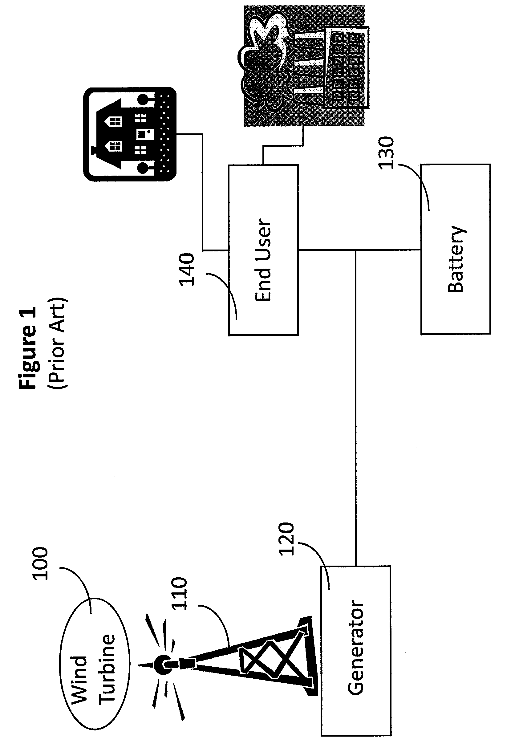
[0028]As understood by those in the art, in a VAWT the electrical generator produces electrical energy from a mechanical energy source i.e. the rotation of the blades. An alternator is a generator that converts mechanical energy to alternating electrical current. When the magnetic field around a conductor changes, current or energy is induced in the conductor. Referring to FIG. 3, in a typical alternator (labeled generally as 300), a rotating magnet or rotor 310 turns within stator 320, a stationary set of conductors wound in coils on an iron core. When rotor 310 rotates, its magnetic field cuts across the conductors (or windings) of stator 320, generating electrical current or energy, as the mechanical input causes the rotor to turn. The magnetic field of rotor 310 may be produced by a rotor winding energized with direct current (i.e. a field current) through slip rings and brushes (not shown). If a direct current output is desired (e.g. to charge a battery 330), the alternating cu...


PUM


Abstract

The invention relates to the field of electrical generation and more specifically to the use of a wind turbine for generating electricity. The invention provides a fully integrated vertical axis wind turbine (VAWT) which can be mounted on a cylindrical pole. Rotor blades are disposed on the outside of a permanent magnet generator integral to the VAWT, the rotor blades being coupled directly to a rotating, current inducing set of permanent magnets or rotor for rotation about a stationary, current generating stator. At least three rotor blades are used which are vertically offset from one another.

Description

CROSS-REFERENCE TO RELATED APPLICATIONS[0001]This application is a continuation-in-part of U.S. Ser. No. 12 / 298,472 which is a national phase entry under 35 USC 371 of International Application PCT / CA2007 / 000665 filed Apr. 20, 2007, claiming the benefit of U.S. provisional applications U.S. 60 / 869,860 filed Dec. 13, 2006 and U.S. 60 / 794,094 filed Apr. 24, 2006, the disclosures of which are incorporated herein by reference.TECHNICAL FIELD[0002]The invention relates to the field of electrical generation and more specifically to the use of a wind turbine for generating electricity.BACKGROUND OF THE INVENTION[0003]As those skilled in the art are aware, the availability of energy sources such as coal, oil and natural gas are limited which has resulted in escalating costs for such fuels. This rising cost is significant for residential users and even more significant for commercial users such as manufacturers where such costs could mean the difference between continued operation and bankru...

Claims


Application Information

Patent Timeline
Patent Type & Authority Applications(United States)
IPC IPC(8): F03D9/00
CPCF03D3/065F03D11/04F05B2240/214Y02E10/74H02K7/183Y02E10/465Y02E10/728F05B2240/911F03D13/20Y02E10/46Y02E70/30F03D3/062F03D9/25F03D9/11
Inventor IRELAND, BARRY R.
Owner BRI ENERGY SOLUTIONS
Why Eureka
Try Eureka