Shock absorber strut with steering knuckle

a technology of shock absorber strut and steering knuckle, which is applied in the direction of steering parts, vehicle components, and resilient suspensions, etc., can solve the problems of inability to separate the middle part from the tubular body, and the tubular body is also subject to considerable load

Inactive Publication Date: 2002-02-05
ZF FRIEDRICHSHAFEN AG
View PDF10 Cites 15 Cited by
  • Summary
  • Abstract
  • Description
  • Claims
  • Application Information

AI Technical Summary

Benefits of technology

In a further embodiment, the stop has a middle part which is fastened to the tubular body, and at least one lateral wing extends from the middle part and is designed so as to be at a radial distance from the tubular body. It has proved beneficial if the middle part has two wings, to avoid introducing any torsional forces into the connection between the middle part and the tubular body. Furthermore, a larger bearing surface is available for the steering knuckle.
According to another embodiment, the projection is formed by a tongue which is shaped out of the plane of the middle part. It was found that, when the projection engages into the slot of the steering knuckle at a greater radial distance from the tubular body, higher positioning accuracy is achieved or, conversely, a greater dimensional tolerance in the components used can be permitted.
At the same time, the projection has an S-shaped profile. This embodiment is advantageous in two respects. On the one hand, forming achieves strain hardening which makes it possible for the projection to have a relatively small wall thickness. Furthermore, the outlay in terms of material even for the length of the tongue is more advantageous than that for a simply vertical projection.
Regarding fastening the structural unit composed of the stop and of the projection, it is advantageous if the middle part is connected for positioning to the tubular body by means of contact welding. Contact welding is resistance welding which is executed in a central region of the middle part, and therefore the edges of the middle part remain available for further fastening possibilities.
For shock absorber struts subjected to greater stress, at least one wing may be welded to the tubular body. This embodiment may also be combined with fastening welding of the middle part. A longer weld seam is obtained, which can consequently also transmit higher load.
To allow free choice of the welding method, the wing has a surface of contact with the tubular body. To make the contact surface readily accessible to the welding apparatus, the contact surface is formed on the lateral edge of the wing. It was found to be particularly advantageous if the contact surface is formed by the end face of the lateral edge. The ratio of the outlay in forming relates to the increase in consolidation and is particularly favorable.

Problems solved by technology

The tubular body is also subjected to considerable load, namely the amount of clamping force or load required to ensure a secure connection.
Even when heat is generated on one side, the middle part cannot separate from the tubular body due to the fastening weld.

Method used


Image

  • Shock absorber strut with steering knuckle
  • Shock absorber strut with steering knuckle
  • Shock absorber strut with steering knuckle

Examples


Embodiment Construction

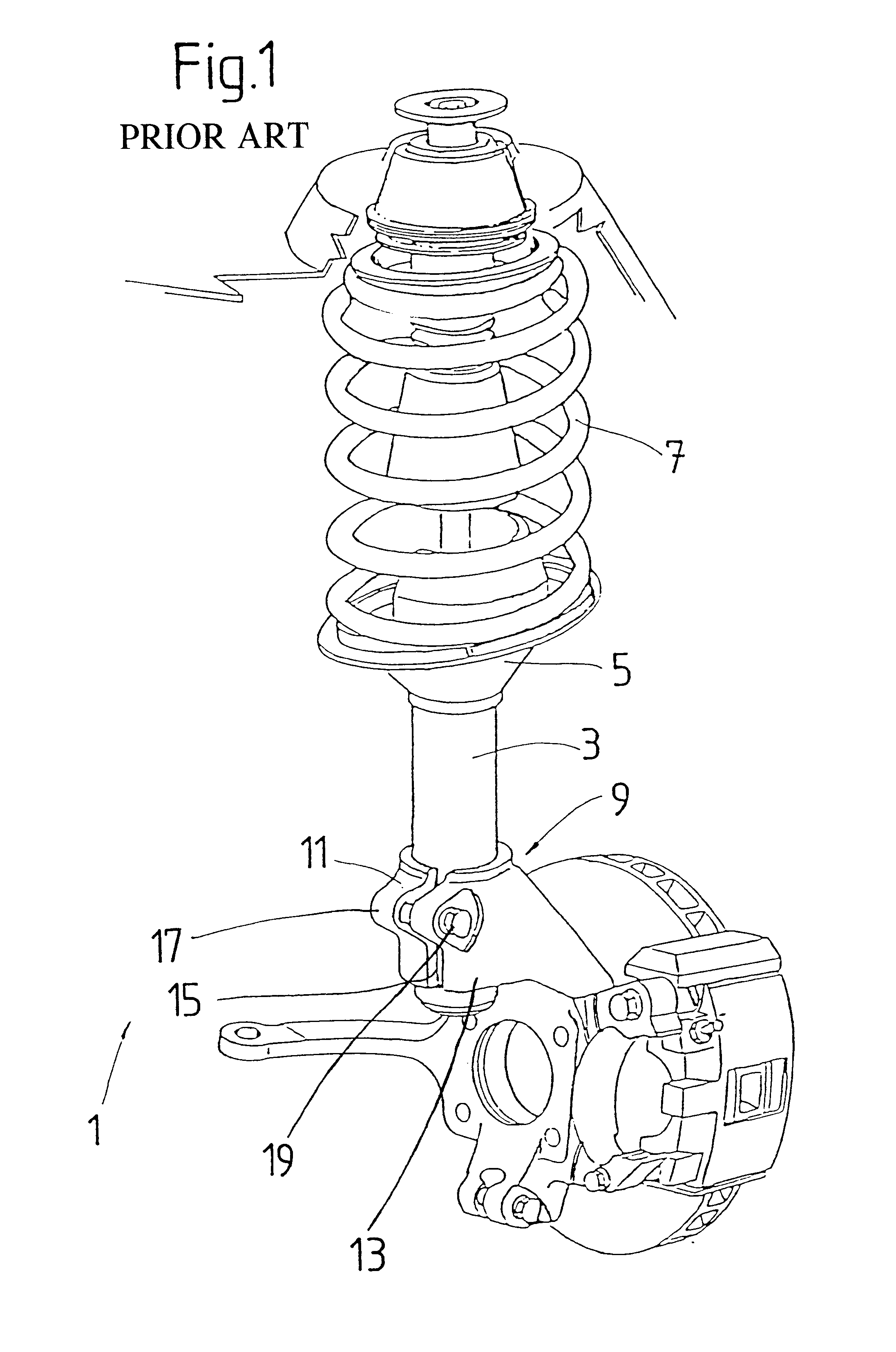
FIG. 1 shows a shock absorber strut 1, such as is used particularly in vehicles of the compact class. The shock absorber strut has a spring plate 5 which, as a rule, is welded to a tubular body 3 and on which a vehicle suspension spring 7 is supported. A steering knuckle 9 is fastened by means of a clamping connection 11 to the lower end of the tubular body 3.

The steering knuckle has a sleeve portion 13 which has a slot 15 essentially parallel to the longitudinal axis of the shock absorber strut. The slot 15 gives the sleeve portion elasticity in the circumferential direction. In the region of the slot, the sleeve portion is provided with a projection 17 having a passage orifice which runs transversely to the longitudinal axis of the shock absorber strut and which comprises a threaded part. A fastening means 19 in the form of a tension screw is screwed in the passage orifice.

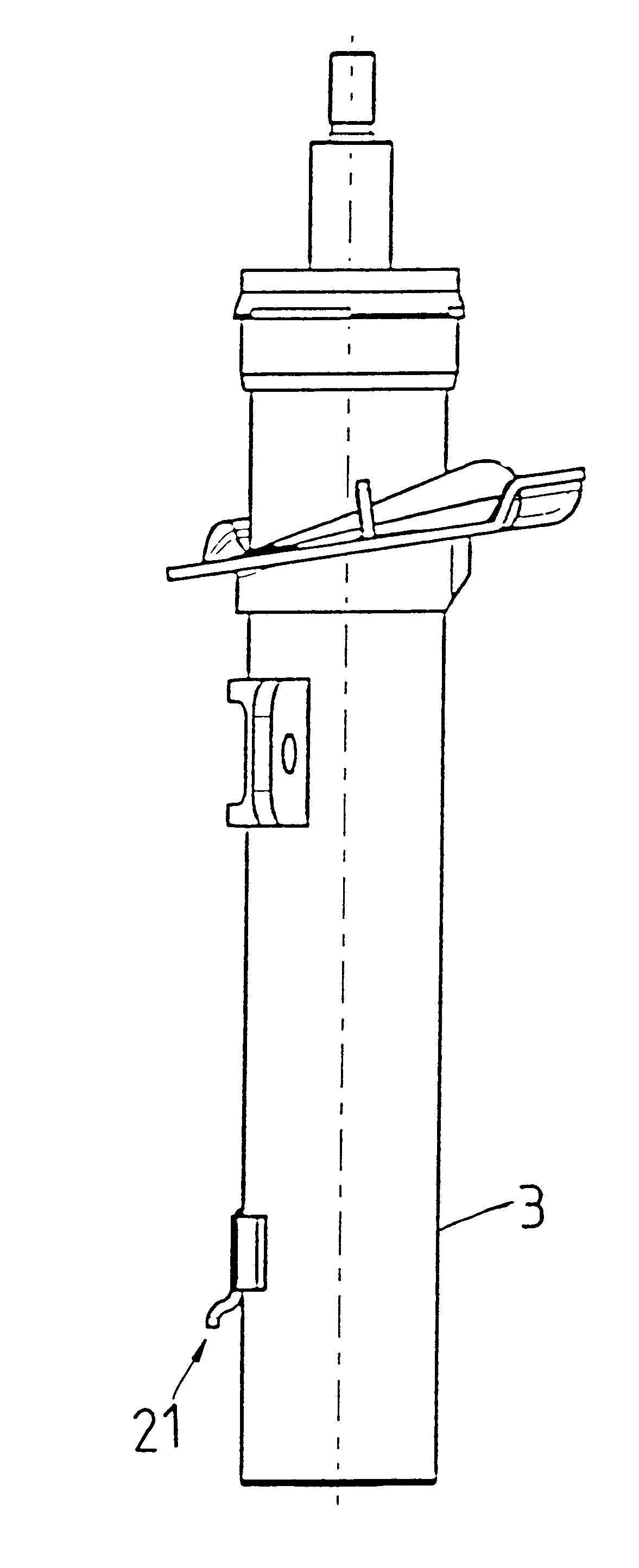
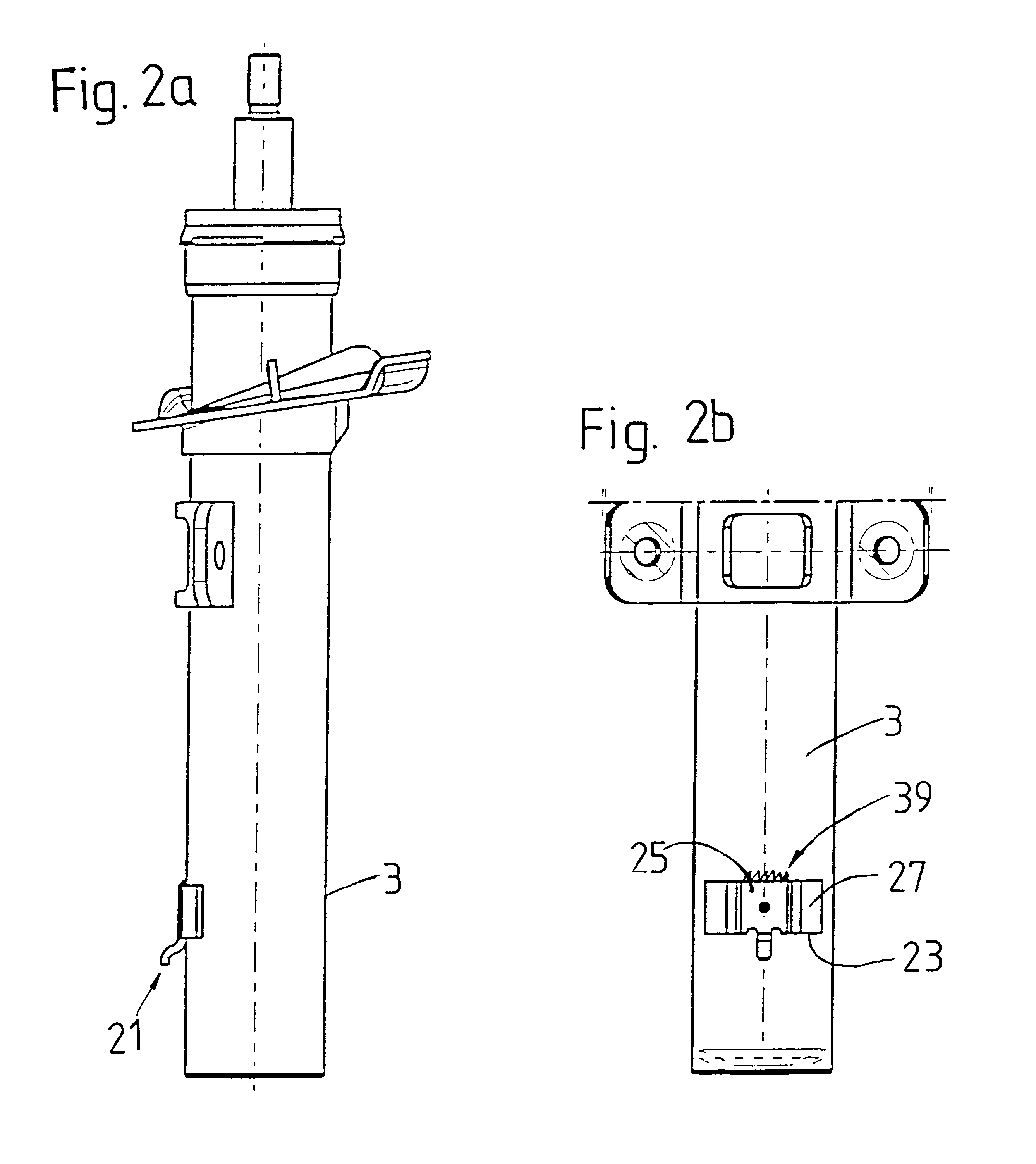
FIGS. 2a and 2b illustrate two views of the tubular body as an individual part. Fastened in the lower region ...


PUM


Abstract

A shock absorber strut is provided including a tubular body, a clamping member, a steering knuckle, a fastening member and a positioning member. The tubular body is arranged at a lower region of the strut. The clamping member clamps the steering knuckle to the tubular body and includes a continuous slot along the steering knuckle and a fastening member which fastens the steering knuckle tubular body. The positioning member is a one piece component for positioning the clamping member with respect to the tubular body and includes a stop for positioning in the longitudinal direction and a projection for positioning in a circumferential direction. Optionally, a further positioning connection may be provided including a bead on the positioning member and a corresponding recess in the tubular body which engages the bead and allows the clamping member to be exactly aligned in the circumferential direction. Various welding processes performed on the positioning member and / or the positioning connection provide further strength and support to the strut.

Description

1. Field of the InventionThe invention relates to a shock absorber strut with a steering knuckle. More particularly, the present invention is a shock absorber strut in which a steering knuckle forms a reliable connection to the tubular body by a clamping means and a positioning means, where the positioning means includes a projection and a stop.2. Description of the Related ArtGerman reference DE 198 15 215 A1 discloses a shock absorber strut with a steering knuckle. The shock absorber strut has a tubular body. A screw connection fastens the steering knuckle to the tubular body. The steering knuckle has a continuous slot which, together with fastening means, forms a clamping connection to the tubular body. A positioning connection having a projection and a recess is between the tubular body and the steering knuckle. The positioning connection makes it possible for the components forming the clamping connection to be perfectly aligned with one another in the circumferential direction...

Claims


Application Information

Patent Timeline
Patent Type & Authority Patents(United States)
IPC IPC(8): B60G15/07B60G13/00B60G15/00
CPCB60G13/006B60G15/07B60G2204/4305B60G2204/129
Inventor HANDKE, GUNTHERBERGEN, FRANK VON DEN
Owner ZF FRIEDRICHSHAFEN AG
Why Eureka
Try Eureka