Motor control apparatus

A motor control and motor speed technology, applied in motor control, motor generator control, AC motor control, etc., can solve the problems of mechanical system shock, output torque sudden change, torque constant change, etc., to achieve safe deceleration characteristics, The effect of improving torque reduction and good acceleration characteristics

Inactive Publication Date: 2014-08-06
SANYO DENKI CO LTD
View PDF6 Cites 17 Cited by
  • Summary
  • Abstract
  • Description
  • Claims
  • Application Information

AI Technical Summary

Problems solved by technology

[0017] However, in the case of the invention described in Patent Document 1, there is a problem that if the magnetic flux command is changed between power running and regeneration, the magnetic flux suddenly changes and the torque constant is changed when the power running is changed to regeneration. Change, in the case of output torque, the sudden change of the output torque of the motor brings impact to the mechanical system

Method used


Image

  • Motor control apparatus
  • Motor control apparatus
  • Motor control apparatus

Examples


Embodiment approach 1

[0062] [Overall Structure of Motor Control Device 100]

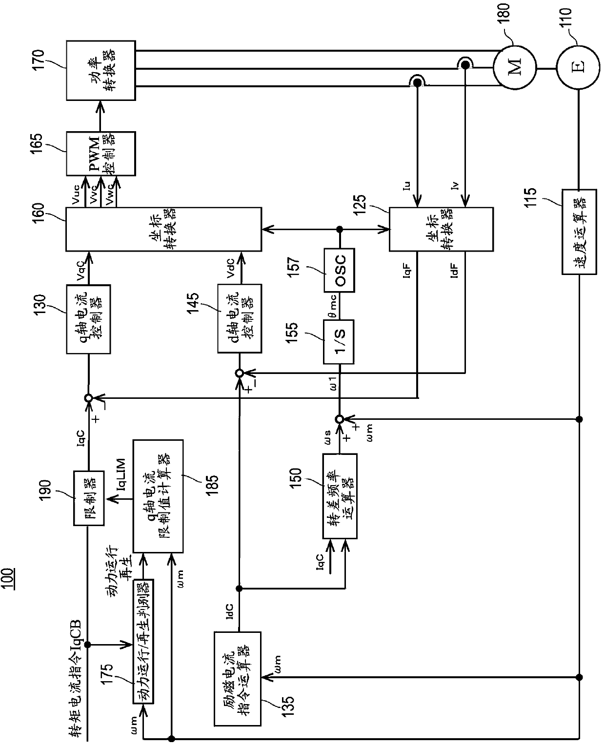
[0063] figure 1 It is a block diagram of the motor control device 100 of Embodiment 1.

[0064] The motor control device 100 includes a q-axis current controller 130 , a power running / regeneration discriminator 175 , a q-axis current limit value calculator 185 , and a limiter 190 as a system for giving a q-axis voltage command VqC.

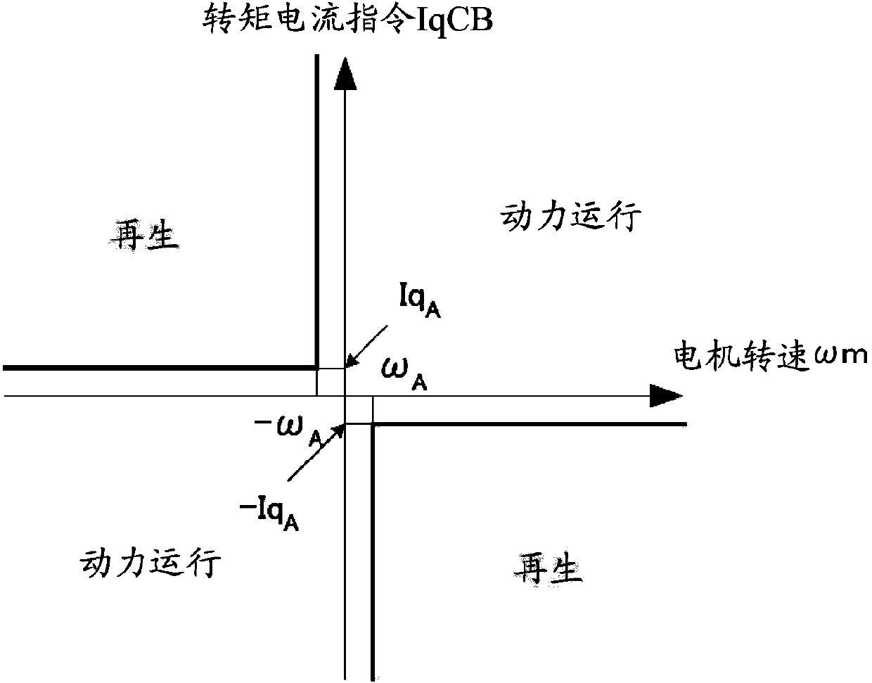
[0065] The power running / regeneration determiner 175 determines whether the motor 180 is in the power running state or in the regenerative state based on the torque current command IqCB and the motor rotation speed ωm. The motor rotation speed ωm is output by the speed calculator 115 . The speed calculator 115 calculates the motor rotational speed ωm using the position feedback detected by the encoder 110 . Note that the detailed operation of power running / regenerating determiner 175 will be described later.

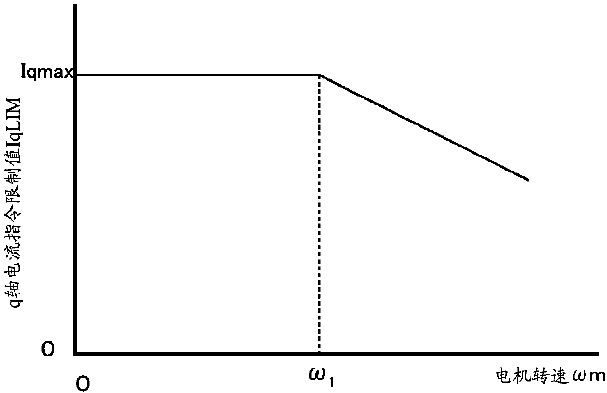
[0066] The q-axis current limit value calculator 185 calculates the q-axis cu...

Embodiment approach 2

[0128] [Overall Structure of Motor Control Device 200]

[0129] Image 6 It is a block diagram of the motor control device 200 of Embodiment 2. The motor control device 200 of Embodiment 2 adds a magnetic flux controller and a magnetic flux calculator to the configuration of the motor control device 100 of Embodiment 1, and includes a magnetic flux command calculator instead of the field current command calculator 135 .

[0130] The motor control device 200 includes a q-axis current controller 230 , a power running / regeneration discriminator 275 , a q-axis current limit value calculator 285 , and a limiter 290 as a system for giving a q-axis voltage command VqC. The q-axis current controller 230, the power running / regeneration discriminator 275, the q-axis current limit value calculator 285, and the limiter 290 are the same as the q-axis current controller 130, the power running / regeneration discriminator 175, and the q-axis current The limit value calculator 185 and the lim...

Embodiment approach 3

[0182] [Overall Structure of Motor Control Device 300]

[0183] Figure 9 It is a block diagram of the motor control device 300 of Embodiment 3. The motor control device 300 of the third embodiment adds a maximum primary current command calculator, a torque limit value calculator, and a q-axis current calculator to the configuration of the motor control device 200 of the second embodiment.

[0184] The motor control device 300 is a system that provides a q-axis voltage command VqC, and includes a q-axis current controller 330 , a power running / regeneration discriminator 375 , a maximum primary current command calculator 383 , a torque limit calculator 385 , and a limiter 390 and a q-axis current calculator 395 . The q-axis current controller 330 and the power running / regeneration discriminator 375 are the same as the q-axis current controller 230 and the power running / regeneration discriminator 275 of the second embodiment.

[0185] The maximum primary current command calcu...


PUM


Abstract

The invention provides a motor control apparatus. A power running / regeneration discriminator (175) uses a torque current command IqCB and a motor rotating speed [omega]m to identify a power running / regeneration status. A limiter (190) enables the torque current command IqCB to pass when a motor (180) is in a power running status, and in a regeneration status, limits the magnitude of the torque current command IqCB according to a limit value IqLIM and enables the torque current command IqCB to pass. A field current command arithmetic unit (135) uses the motor rotating speed [omega]m to identify a rotation status of the motor (180) and calculates a field current command IdC corresponding to the rotation status. A motor drive part (q-axis current controller (130), d-axis current controller (145), a coordinate converter (160), a PWM controller (165) and a power converter (170)) uses the torque current command IqC passed from the limiter and the calculated field current command IdC to drive the motor (180).

Description

technical field [0001] The present invention relates to a motor control device with improved acceleration and deceleration characteristics in vector control of an induction motor. Background technique [0002] The spindle of the machine tool requires both low-speed heavy cutting and high-speed cutting. Therefore, high torque at low speed rotation and high speed rotation are realized by constant output control of field weakening. As a motor control device that performs constant output control, a device configured as follows can be exemplified. [0003] Figure 12 is a block diagram of an existing motor control device. The motor control device works as follows. [0004] First, the speed command is compared with the motor rotation speed ωm from the speed calculator 15 , and the q-axis current command IqC is obtained by the speed controller 20 . The motor rotation speed ωm output by the speed calculator 15 is calculated using the position feedback detected by the encoder 10 ...

Claims


Application Information

Patent Timeline
Patent Type & Authority Applications(China)
IPC IPC(8): H02P21/00H02P21/05H02P21/22H02P21/36H02P23/04H02P23/07H02P23/16H02P23/18H02P27/04H02P27/06H02P27/08
CPCH02P3/14H02P21/06H02P21/20H02P27/04H02P29/02
Inventor 井出勇治山崎悟史
Owner SANYO DENKI CO LTD
Why Eureka
Try Eureka