Method for selecting source transmit antenna in cooperative MIMO communication system

a communication system and source transmit antenna technology, applied in the field of source transmit antenna selection in the cooperative multipleinput and multipleoutput (mimo) communication system, can solve the problems of difficulty in derive accurate signal-to-noise (snr), and high cost of rf chain size, etc., to achieve the effect of improving the lowered transmit performance and accurate performance standards

Active Publication Date: 2012-07-19
DONGGUK UNIV IND ACADEMIC COOPERATION FOUND
View PDF2 Cites 2 Cited by
  • Summary
  • Abstract
  • Description
  • Claims
  • Application Information

AI Technical Summary

Benefits of technology

[0009]The present invention is directed to providing an accurate performance standard in selecting a source transmit antenna in a cooperative communication system, to improving a lowered transmit performance due

Problems solved by technology

However, the use of space-time code needs highly priced RF chains as many as the number of multiple antennas.
The RF chain is known to be costly in terms of size, power consumption and hardware.
Unlike amplify-and-

Method used


Image

  • Method for selecting source transmit antenna in cooperative MIMO communication system
  • Method for selecting source transmit antenna in cooperative MIMO communication system
  • Method for selecting source transmit antenna in cooperative MIMO communication system

Examples


first embodiment

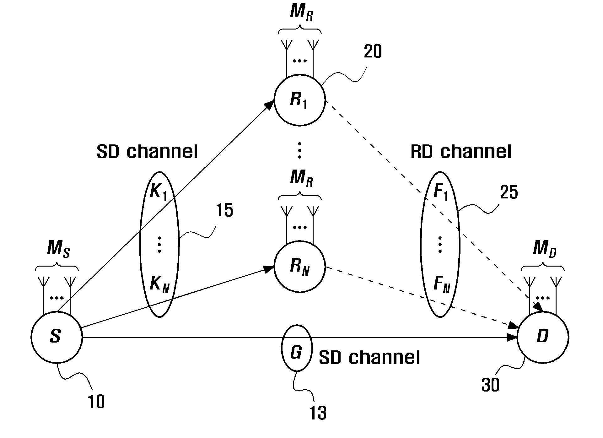
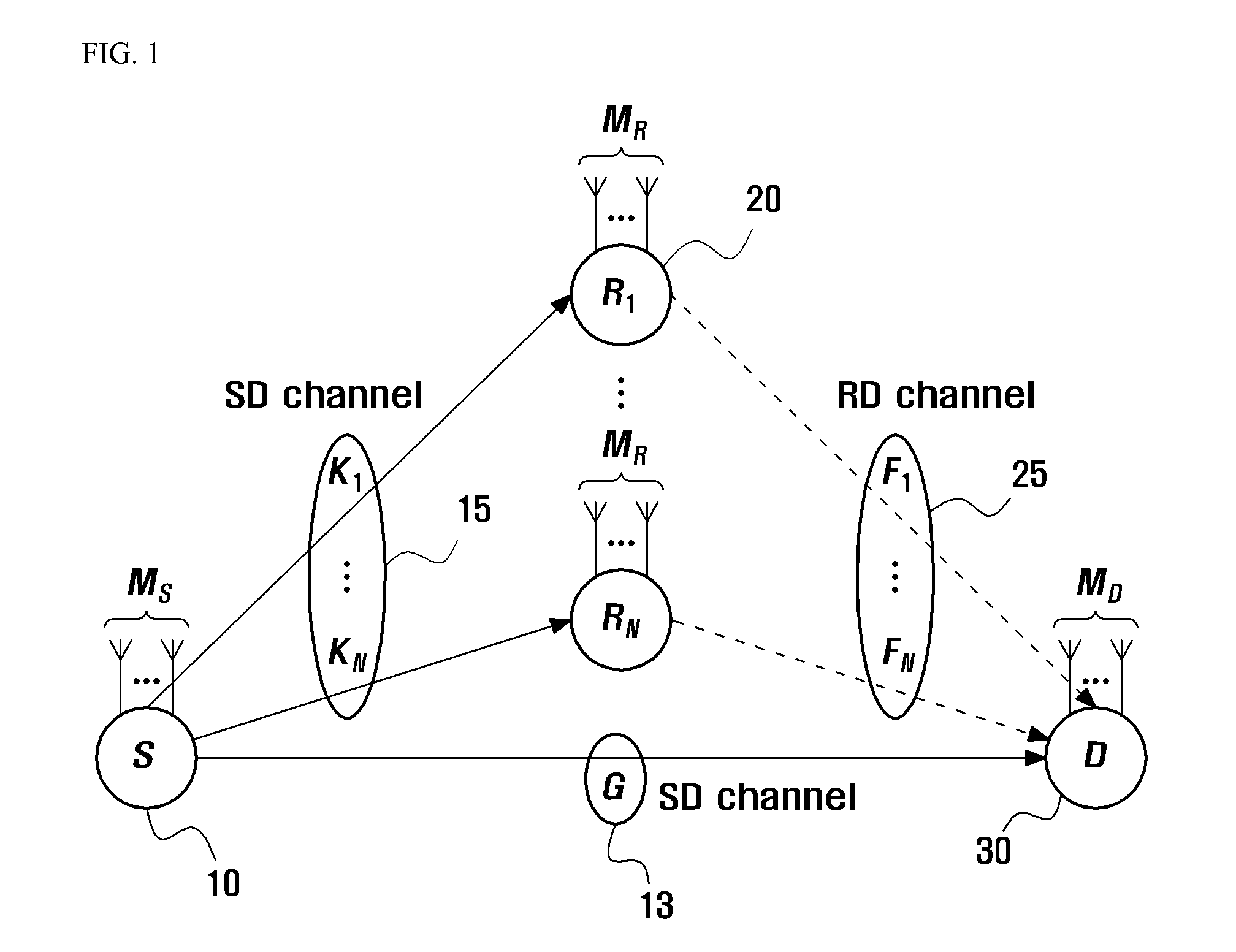
[0047]In a first embodiment, suppose that a single antenna is selected at the source node and an encoding is not performed. In this case, the source transmit antenna selection metric set in Expression 2 is expressed by Expression 3:

Γj=PSG(j)2+∑i=1Nmin[PS2Ki(j)2,PRminx,x⋁≠xFi(XR(x)-XR(x⋁))2](3)

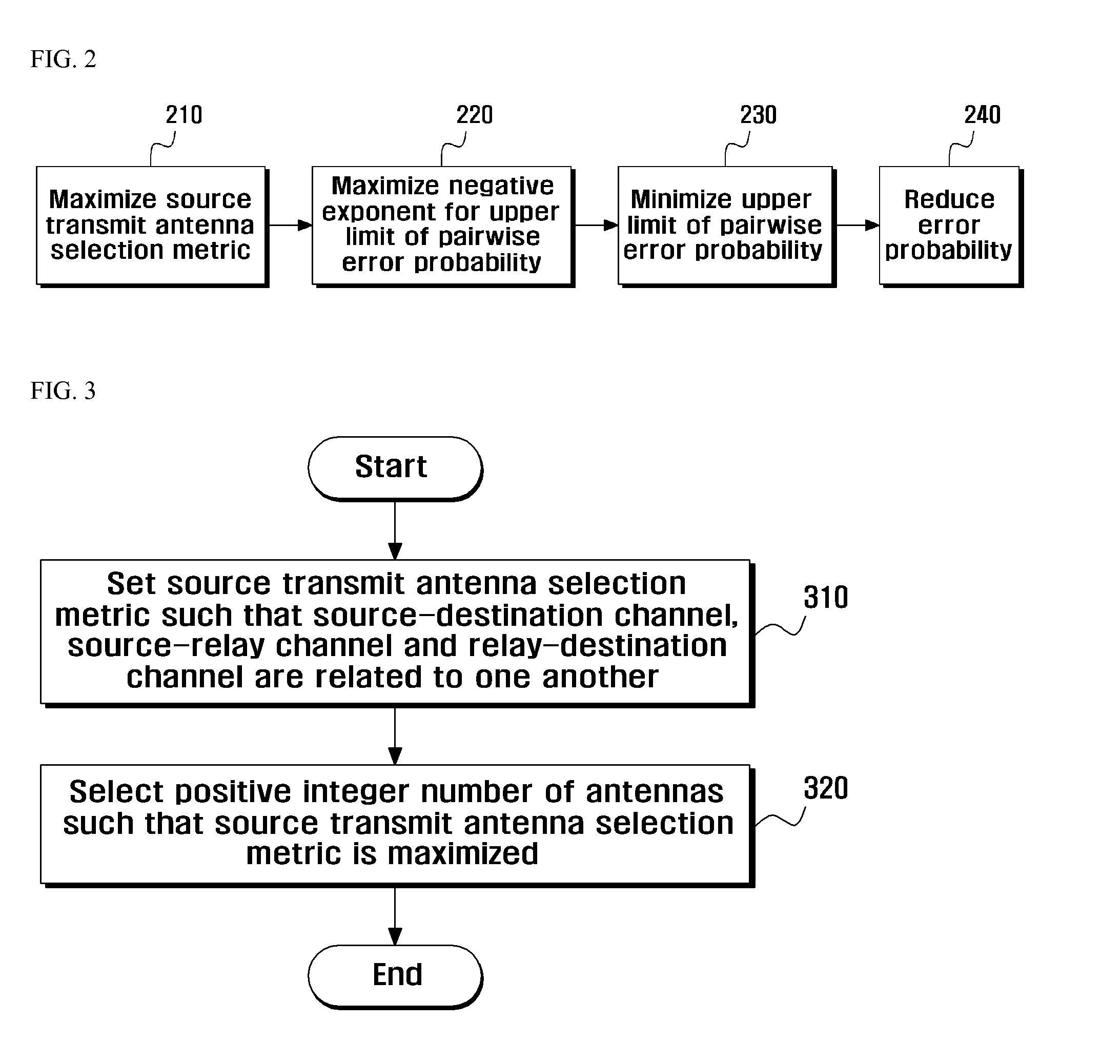
[0048]In this case, the present embodiment selects a single antenna to maximize the source transmit antenna selection metric set in Expression 3.

second embodiment

[0049]In a second embodiment, suppose that a single antenna is selected at each of the source node and the relay node and an encoding is not performed. In this case, the source transmit antenna selection metric set in Expression 2 is expressed by Expression 4:

Γj=PSG(j)2+∑i=1Nmin[PS2Ki(j)2,PRFi2](4)

[0050]In this case, the present embodiment selects a single antenna to maximize the source transmit antenna selection metric set in Expression 4.

third embodiment

[0051]In a third embodiment, suppose that both the source node and the relay node use orthogonal space-time code. In this case, the orthogonal space-time code may be Alamouti code, and the source transmit antenna selection metric set in Expression 2 is expressed by Expression 5:

Γj=PSG(j)2+∑i=1Nmin[PS2Ki(j)2,PRFi2](5)

[0052]In this case, the present embodiment selects two antennas to maximize the source transmit antenna selection metric set in Expression 5.

[0053]As discussed above, the present embodiments describe new source transmit antenna selection methods in the decode-and-forward cooperative communication system. It has been experimentally shown that these methods may yield a lower error probability than a conventional method. Experiment results will be shown with reference to FIGS. 4 to 6.

[0054]FIG. 4 illustrates experimental results when a single antenna is selected at a source node in accordance with a method of selecting a source transmit antenna according to an embodiment of...


PUM


Abstract

Disclosed is a method for selecting a source transmit antenna in a cooperative multiple-input and multiple-output (MIMO) communication system including a source node, a relay node and a destination node. The method includes determining a source transmit antenna selection metric such that a source-destination channel, a source-relay channel and a relay-destination channel are related to one another, and selecting a positive integer number of antennas such that the source transmit antenna selection metric is maximized.

Description

CROSS-REFERENCE TO RELATED APPLICATIONS[0001]This application claims priority under 35 U.S.C. §119 to Korean Patent Application No. 10-2011-0004243, filed on Jan. 14, 2011, in the Korean Intellectual Property Office, the disclosure of which is incorporated herein by reference in its entirety.BACKGROUND[0002]1. Field of the Invention[0003]The present invention relates to a method for selecting a source transmit antenna in a cooperative multiple-input and multiple-output (MIMO) communication system. More particularly, the present invention relates to a method for selecting a source transmit antenna in a cooperative MIMO communication system for transmitting a signal from a source node to a destination node through a relay node and a computer-readable medium for recording the method thereon.[0004]2. Description of Related Art[0005]In recent years, much research on cooperative communication systems has been conducted to improve the spectral efficiency and reliability of communication sy...

Claims


Application Information

Patent Timeline
IPC IPC(8): H04B1/04
CPCH04B7/024H04B7/15H04B7/0691H04B7/0413
Inventor LIM, DAE WOONSHIN, DONG-JOONNO, JONG-SEONJIN, XIANGLAN
Owner DONGGUK UNIV IND ACADEMIC COOPERATION FOUND
Why Eureka
Try Eureka