Photovoltaic Roofing Elements and Photovoltaic Roofing Systems

a technology of photovoltaic roofing and photovoltaic roof, which is applied in the direction of snow traps, light and heating equipment, heat collector mounting/support, etc., can solve the problems of increasing the cost of fossil fuels, affecting the understanding of embodiments, and affecting the effect of aesthetics

Active Publication Date: 2012-07-26
CERTAIN TEED LLC
View PDF6 Cites 45 Cited by
  • Summary
  • Abstract
  • Description
  • Claims
  • Application Information

AI Technical Summary

Problems solved by technology

First, fossil fuels have become increasingly expensive due to increasing scarcity and unrest in areas rich in petroleum deposits.
Second, there exists overwhelming concern about the effects of the combustion of fossil fuels on the environment due to factors such as air pollution (from NOx, hydrocarbons and ozone) and global warming (from CO2).
While stand-alone photovoltaic modules have been in use for some time, they tend to be heavy and bulky, and aesthetically unfavorable when installed on a roof.
These can be very advantageous, but can be difficult to install on steep surfaces, while ensuring sufficient closure of the roof against the elements, particularly wind driven rain, and can often result in incomplete coverage of the roof surface with photovoltaic power generation.
But in many systems, the wiring is at risk of being dislocated, being damaged, or being pinched or bent into a radius tighter than allowed by code during handling and installation.
This risk is especially high when the photovoltaic roofing element includes support structures such as downward-facing ribs, as the installer may not be able to determine if wiring is pinched between the support structure and the underlying roof deck.
Damaged wire can cause power loss over time, injury, or fire, and is therefore undesirable.

Method used


Image

  • Photovoltaic Roofing Elements and Photovoltaic Roofing Systems
  • Photovoltaic Roofing Elements and Photovoltaic Roofing Systems
  • Photovoltaic Roofing Elements and Photovoltaic Roofing Systems

Examples


Embodiment Construction

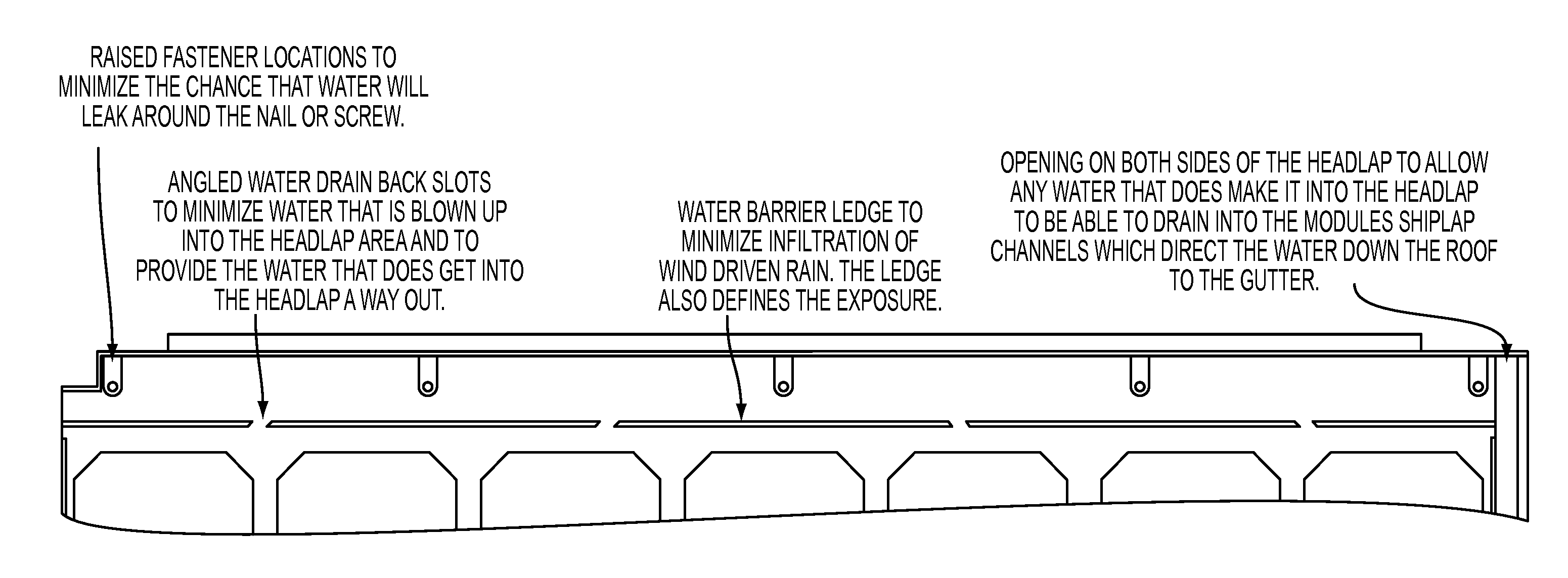
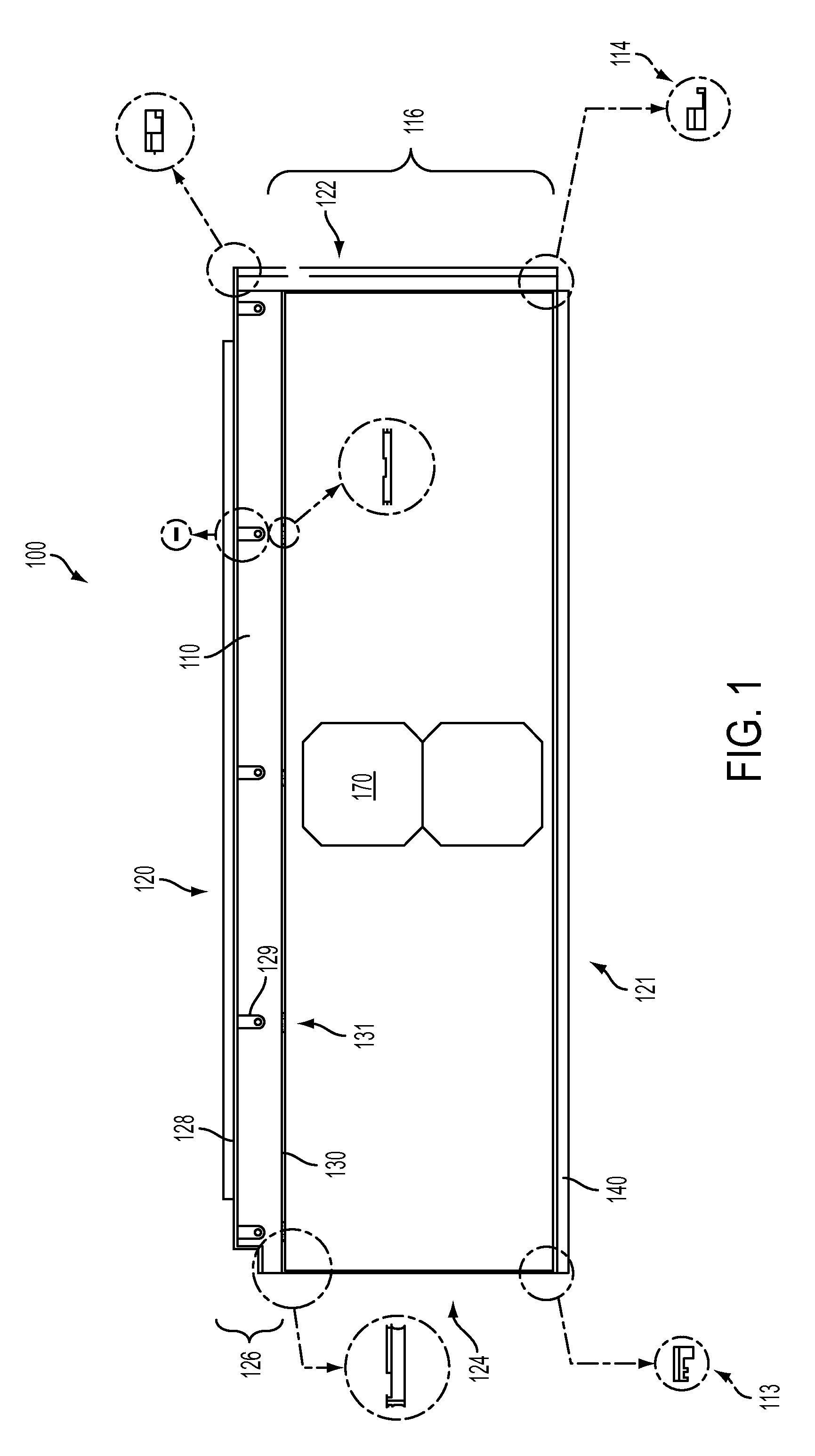
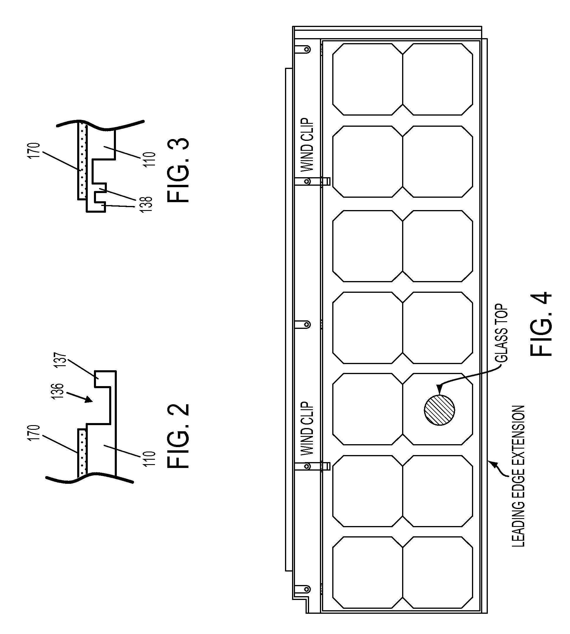
[0057]One aspect of the invention is a photovoltaic roofing element, configured to be disposed on a roof deck having a top end (i.e., toward the ridge of the roof) and a bottom end (i.e., toward the eave of the roof). The photovoltaic roofing element includes a frame structure having an upward-facing surface and a downward-facing surface. The frame structure includes an attachment zone and an exposure zone, with the exposure zone disposed toward the bottom end of the frame structure, and the attachment zone disposed toward the top end of the frame structure. The photovoltaic roofing element further includes one or more photovoltaic elements held in the frame structure.

[0058]In certain embodiments, the frame structure includes sidelap portions disposed at its lateral edges and having geometries adapted to interlock with adjacent photovoltaic roofing elements to provide water drainage channels. For example, in one embodiment, the sidelap portion at one lateral edge has an upward-facin...


PUM

PropertyMeasurementUnit
sizeaaaaaaaaaa
thicknessaaaaaaaaaa
heightaaaaaaaaaa

Abstract

The present invention relates generally to the photovoltaic generation of electrical energy. The present invention relates more particularly to photovoltaic arrays for use in photovoltaically generating electrical energy. Aspects of the present invention provide a variety of photovoltaic roofing elements and systems that include, for example, interlocking geometries to provide for water handling and integration with conventional roofing materials; and wire management features that can protect wiring and associated electrical components from physical and / or environmental damage.

Description

CROSS-REFERENCE TO RELATED APPLICATIONS[0001]The present application claims priority to U.S. Provisional Patent Application Ser. No. 61 / 429,053; U.S. Provisional Patent Application Ser. No. 61 / 528,631; and U.S. Provisional Patent Application Ser. No. 61 / 559,614, each of which is hereby incorporated herein by reference in its entirety.BACKGROUND OF THE INVENTION[0002]1. Field of the Invention[0003]The present invention relates generally to the photovoltaic generation of electrical energy. The present invention relates more particularly to photovoltaic roofing products for use in photovoltaically generating electrical energy.[0004]2. Technical Background[0005]The search for alternative sources of energy has been motivated by at least two factors. First, fossil fuels have become increasingly expensive due to increasing scarcity and unrest in areas rich in petroleum deposits. Second, there exists overwhelming concern about the effects of the combustion of fossil fuels on the environment...

Claims


Application Information

Patent Timeline
Patent Type & Authority Applications(United States)
IPC IPC(8): H01L31/0203B23P11/00H01L31/048
CPCY02B10/12Y02E10/50E04D13/1415E04D13/04H01L31/048F24J2/5245H02S20/00H02S20/23H02S20/25Y10T29/49826H01L31/0483H01L31/0482H01L31/0422Y02B10/20E04B1/7069Y02E10/47Y02B10/10E04D1/12E04D1/2916E04D1/30E04D2001/308E04D13/16E04D13/158F24S25/61E04D13/00H01L31/0481
Inventor JENKINS, ROBERT L.FISHER, CHRISTOPHER C.LIVSEY, ROBERT D.
Owner CERTAIN TEED LLC
Why Eureka
Try Eureka