Hydraulic Drilling Method with Penetration Control

a technology of hydraulic drilling and control, applied in the direction of drilling machines and methods, drilling accessories, borehole/well accessories, etc., can solve the problems of cable breakage, system failure, and difficulty in precisely controlling the penetration rate of drill strings

Active Publication Date: 2012-07-26
PETROJET CANADA
View PDF9 Cites 17 Cited by
  • Summary
  • Abstract
  • Description
  • Claims
  • Application Information

AI Technical Summary

Problems solved by technology

Under significant tension the cable (whether holding back the drill string or while being used to retract the drill string) will stretch, making it difficult to precisely control the rate of penetration of the drill string.
There is also a possibility that the cable may break, which would necessitate shutting down the drilling operation to recover the drill head, repair the cable, and possibly also repair or replace the drill head in the event that it is damaged by impacting ...

Method used


Image

  • Hydraulic Drilling Method with Penetration Control
  • Hydraulic Drilling Method with Penetration Control
  • Hydraulic Drilling Method with Penetration Control

Examples


Embodiment Construction

[0013]The detailed description set forth below in connection with the appended drawings is intended as a description of various embodiments of the present invention and is not intended to represent the only embodiments contemplated by the inventor. The detailed description includes specific details for the purpose of providing a comprehensive understanding of the present invention. However, it will be apparent to those skilled in the art that the present invention may be practiced without these specific details.

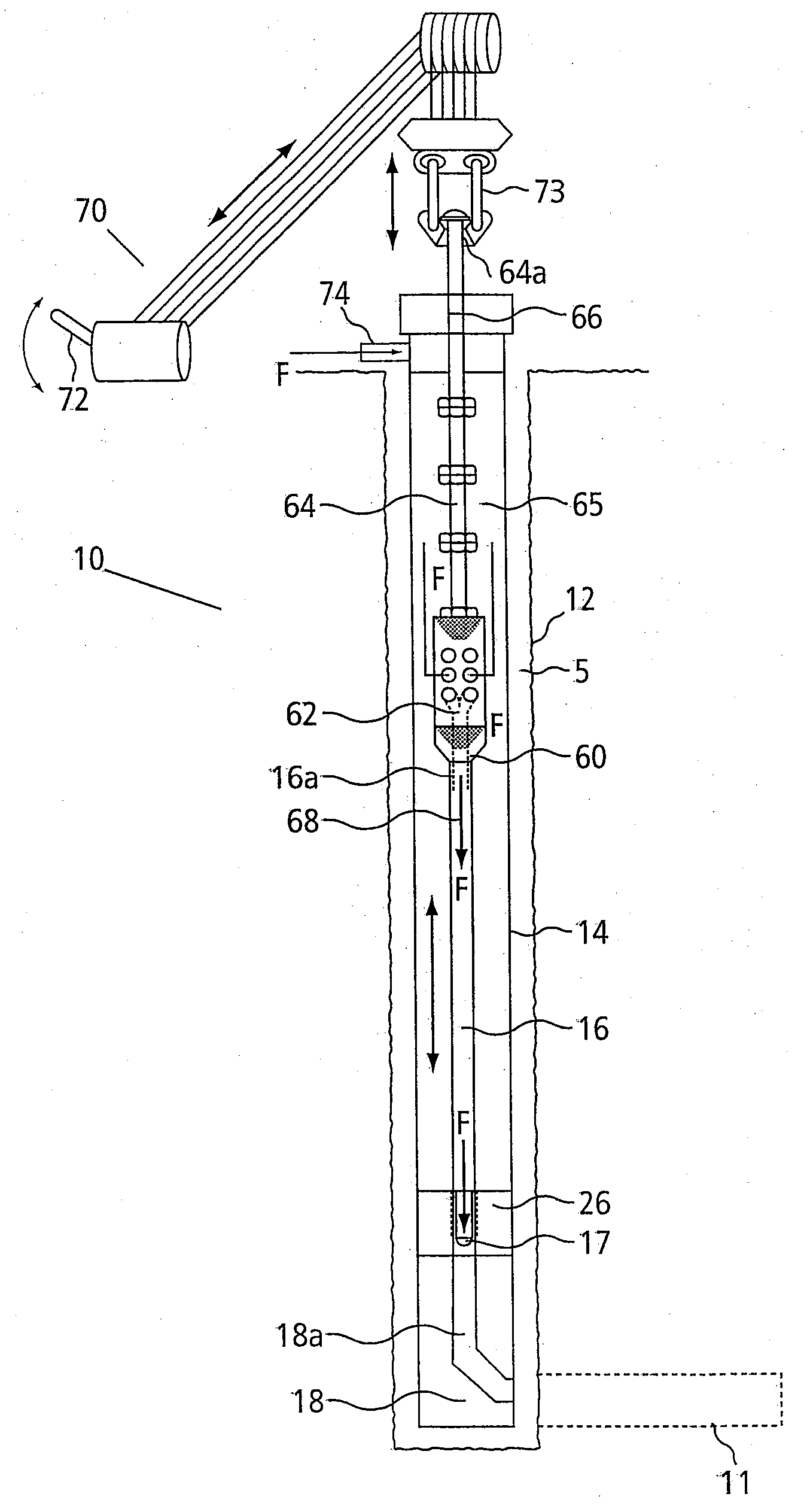
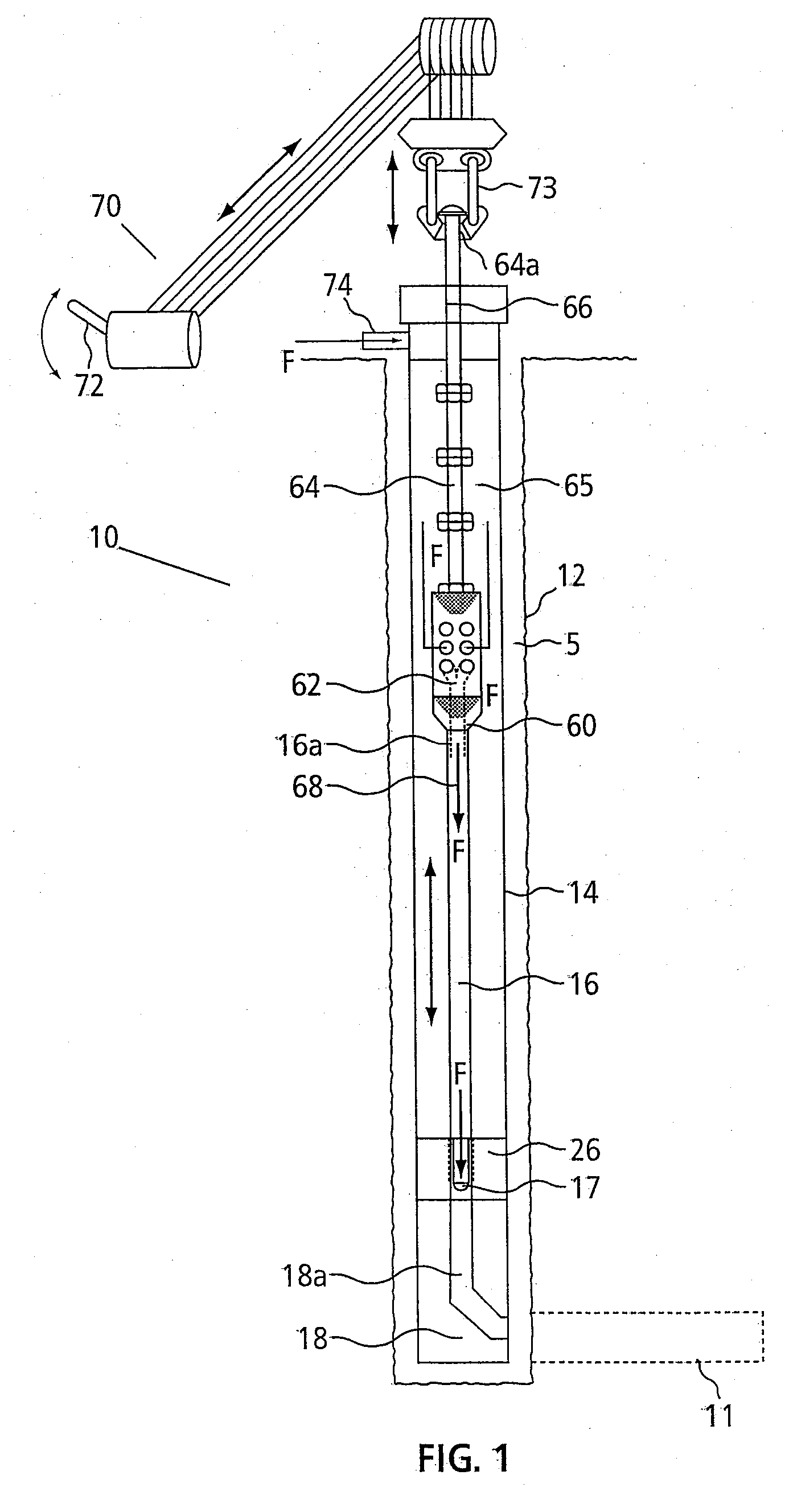
[0014]FIG. 1 illustrates a drilling apparatus in one aspect. In FIG. 1, the apparatus is illustrated in connection with the drilling of a lateral bore hole 11, shown in phantom, which extends from a main borehole 12 in the earth. Main borehole 12 can be vertical, deviated or horizontal and may be the borehole extending from surface or a lateral therefrom.

[0015]The drilling apparatus 10 can include a tubular work string 14 which extends in the main borehole 12. A whipstock 18 ...


PUM


Abstract

A system and method for hydraulic drilling is provided. A whipstock having a bore can be sealingly engaged at a distal end of a workstring. A drilling apparatus having drill tubing and a flow through device for routing drilling fluid into the drill tubing can be connected to the end of a connection string and inserted down into the work string so that the drill tubing extends through the bore in the whipstock device. Pressurized drilling fluid can then be inserted into the annulus formed between the work string and the connection string so that the pressurized drilling fluid passes through the flow through device into the drilling tube and is discharged out the distal end of the drilling tube as a cutting jet.

Description

[0001]This invention pertains generally to hydraulic drilling apparatuses and methods and, more particularly, to a system and method for supplying drilling fluid downhole for hydraulic drilling.BACKGROUND OF THE INVENTION[0002]In hydraulic drilling operations, a highly pressurized drilling fluid is discharged through a drill head as a high velocity cutting jet which cuts away the material at which it is directed to form a borehole. As the material is removed, the drill head is advanced to extend the borehole into the earth. The drill head is typically attached to a tubular work string to which the pressurized fluid is applied, and the force exerted on the work string and head by the fluid drives them in the forward direction. The rate at which the drill head advances is limited by a cable which is attached to the work string and played out at a controlled rate.[0003]The use of the restraining cable has certain limitations and disadvantages. It requires not only the cable itself but ...

Claims


Application Information

Patent Timeline
IPC IPC(8): E21B7/00E21B41/00
CPCE21B44/02E21B7/18E21B7/061
Inventor MCDOUGALL, MYLESNIELSEN, JEREMYTATMAN, CARL
Owner PETROJET CANADA
Why Eureka
Try Eureka