Liquid-crystal panel equipped with touch sensor function

a technology of touch sensor and liquid crystal panel, which is applied in the field can solve the problems of troublesome manufacturing of projecting electrodes, rise in manufacturing costs, and difficulty in adjusting the sensitivity of liquid crystal panel equipped with touch sensor function, so as to achieve the effect of adjusting the sensitivity of pressing force detection

Inactive Publication Date: 2012-07-26
SHARP KK
View PDF3 Cites 42 Cited by
  • Summary
  • Abstract
  • Description
  • Claims
  • Application Information

AI Technical Summary

Benefits of technology

[0014]According to this embodiment of the present invention, it is possible to provide a liquid crystal panel equipped with a touch sensor function that can detect the intensity of pressing force in addition to a pressing force position. Moreover, it is possible to adjust the sensitivity of pressing force detection without changing a manufacturing step.

Problems solved by technology

Specifically, it is necessary to create a new mask to be used in the projecting electrode manufacturing step, and change the exposure conditions in photolithography, thus making the manufacturing of the projecting electrodes troublesome and causing a rise in manufacturing cost.
It is therefore difficult for the sensitivity of the liquid crystal panel equipped with a touch sensor function to be adjusted according to the user and the usage scenario.
Accordingly, due to dimensional variation that unavoidably occurs in projecting electrode manufacturing, it is not possible to avoid differences in pressing force detection sensitivity between each product.
However, there is a limit on how low dimensional variation can be reduced, and the number of types of projecting electrodes that can actually be manufactured is also limited, and therefore there is a limit on resolution in pressing force detection.

Method used


Image

  • Liquid-crystal panel equipped with touch sensor function
  • Liquid-crystal panel equipped with touch sensor function
  • Liquid-crystal panel equipped with touch sensor function

Examples


embodiment 1

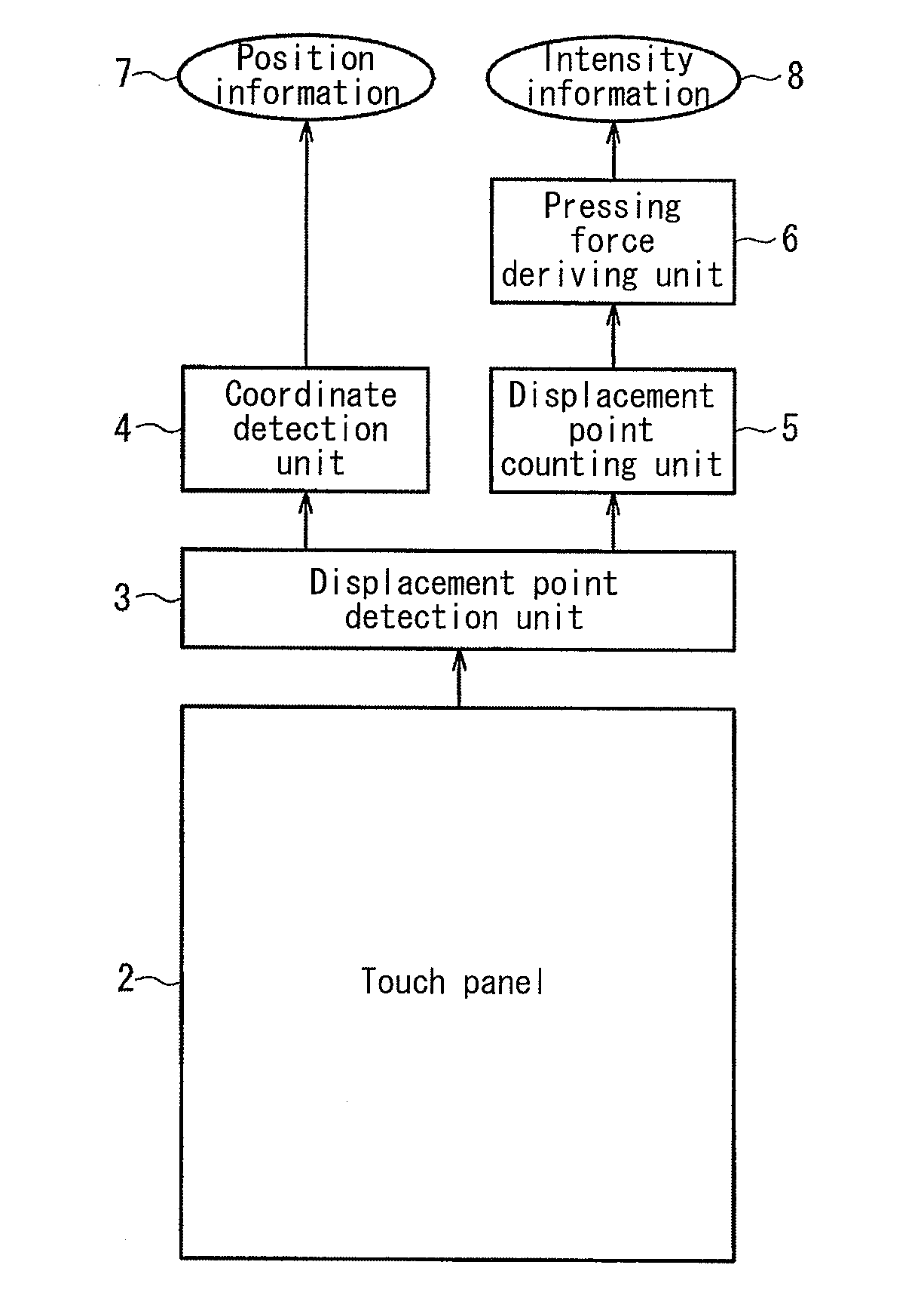
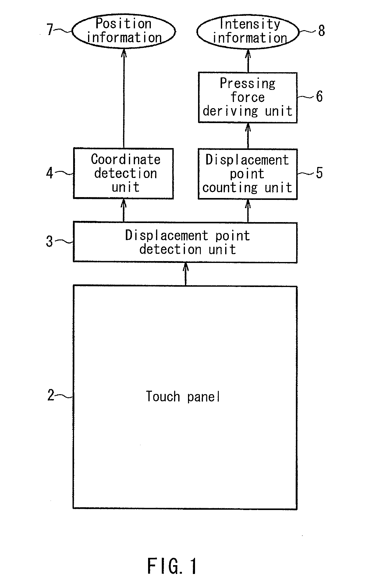
[0055]FIG. 1 is a block diagram of a touch sensor unit of a liquid crystal panel equipped with a touch sensor function according to Embodiment 1.

[0056]The touch sensor unit of the liquid crystal panel equipped with a touch sensor function of Embodiment 1 includes a touch panel 2, a displacement point detection unit 3, a coordinate detection unit 4, a displacement point counting unit 5, and a pressing force deriving unit 6.

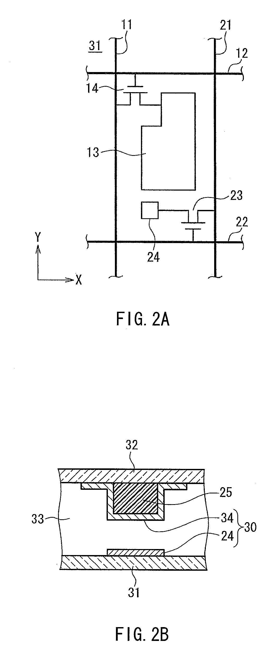
[0057]The touch panel 2 includes a pair of opposing substrates and a plurality of displacement detection units provided between the pair of substrates.

[0058]As the pair of substrates, it is possible to use, for example, a pair of light-transmitting substrates that configure part of the liquid crystal panel and sandwich liquid crystal.

[0059]When the surface (touch surface, which is normally the image display surface) of one substrate (the touch substrate) out of the pair of substrates is pressed, the displacement detection units output a signal in accordance with di...

embodiment 2

[0129]In Embodiment 1, the displacement point counting unit 5 counts the total number of displacement points that constitute the two-dimensionally expanding displacement area shown in FIGS. 6A to 6G. In contrast, in Embodiment 2, the displacement point counting unit 5 counts the number of displacement points that constitute the greatest width in the X axis direction of the displacement area. Specifically, the displacement point counting unit 5 counts the number of displacement points aligned in the X axis direction at the Y axis direction position where the width in the X axis direction of the displacement area is the greatest.

[0130]FIG. 9 is a diagram showing the relationship between the number of displacement points constituting the greatest width in the X axis direction of the displacement area (the greatest number of displacement points in the X axis direction) and the pressing force, which was obtained from FIGS. 6A to 6G. It can be understood from FIG. 9 that, for example, the...

embodiment 3

[0134]In Embodiment 2, the displacement point counting unit 5 counts the number of displacement points that constitute the greatest width in the X axis direction of the displacement area. In contrast, in Embodiment 3, the displacement point counting unit 5 counts the number of displacement points that constitute the greatest width in the Y axis direction of the displacement area. Specifically, the displacement point counting unit 5 counts the number of displacement points aligned in the Y axis direction at the X axis direction position where the width in the Y axis direction of the displacement area is the greatest.

[0135]FIG. 10 is a diagram showing the relationship between the number of displacement points constituting the greatest width in the Y axis direction of the displacement area (the greatest number of displacement points in the Y axis direction) and the pressing force, which was obtained from FIGS. 6A to 6G. It can be understood from FIG. 10 that, for example, the greatest ...


PUM


Abstract

Provided is a liquid crystal panel equipped with a touch sensor function that can detect pressing force. Multiple displacement detection units (30) are provided between a pair of substrates (31, 32) arranged opposing each other and output a signal due to displacement of one of the substrates. A displacement point detection unit (3) binarily detects whether the one substrate has become displaced at each position of the displacement detection units (30) based on the signals output from the displacement detection units (30). A coordinate detection unit (4) detects the coordinates of, among the displacement detection units (30), the displacement detection units for which the displacement point detection unit (3) detected that the one substrate became displaced, and outputs pressing force position information. A displacement point counting unit (5) counts the number of displacement detection units for which the displacement point detection unit (3) detected that displacement occurred among the displacement detection units (30), and a pressing force deriving unit (6) outputs information regarding a pressing force intensity based on the number of displacement detection units counted by the displacement point counting unit (5).

Description

REFERENCE TO RELATED APPLICATIONS[0001]This application is the national stage under 35 USC 371 of International Application No. PCT / JP2010 / 065841, filed Sep. 14, 2010, which claims priority from Japanese Patent Application No. 2009-226877, filed Sep. 30, 2009, the entire contents of which are incorporated herein by reference.FIELD OF THE INVENTION[0002]The present invention relates to a liquid crystal panel equipped with a touch sensor function. In particular, the present invention relates to a liquid crystal panel equipped with a touch sensor function that can detect touch pressure (pressing force) in addition to a touch position (pressing force position).BACKGROUND OF THE INVENTION[0003]Image display devices that can also be used as an information input device by providing the image display surface with a touch sensor function have been put into practical use. With such image display devices, generally a position (touch position) on the image display surface that has been touched ...

Claims


Application Information

Patent Timeline
Patent Type & Authority Applications(United States)
IPC IPC(8): G09G3/36G06F3/041G06F3/044
CPCG02F1/13338G06F3/0412G06F3/047
Inventor TSUJINO, KAZUYAYAMAMOTO, KEIICHI
Owner SHARP KK
Why Eureka
Try Eureka