Zoom lens, optical apparatus and method for manufacturing zoom lens

a technology of optical apparatus and zoom lens, which is applied in the direction of optics, optical elements, instruments, etc., can solve the problems that the conventional zoom lens does not meet the ideal optical performance, and achieve the effect of high zoom ratio, ideal optical performance and large aperture ratio

Active Publication Date: 2012-07-26
NIKON CORP
View PDF1 Cites 2 Cited by
  • Summary
  • Abstract
  • Description
  • Claims
  • Application Information

AI Technical Summary

Benefits of technology

[0029]According to the present invention, an ideal optical performance can be implemented with a wide-angle of view, a large aperture ratio and a high zoom ratio.

Problems solved by technology

This conventional zoom lens, however, does not satisfy the ideal optical performance.

Method used


Image

  • Zoom lens, optical apparatus and method for manufacturing zoom lens
  • Zoom lens, optical apparatus and method for manufacturing zoom lens
  • Zoom lens, optical apparatus and method for manufacturing zoom lens

Examples


example 1

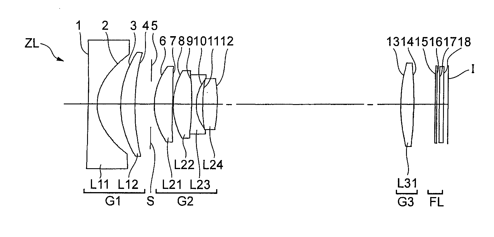
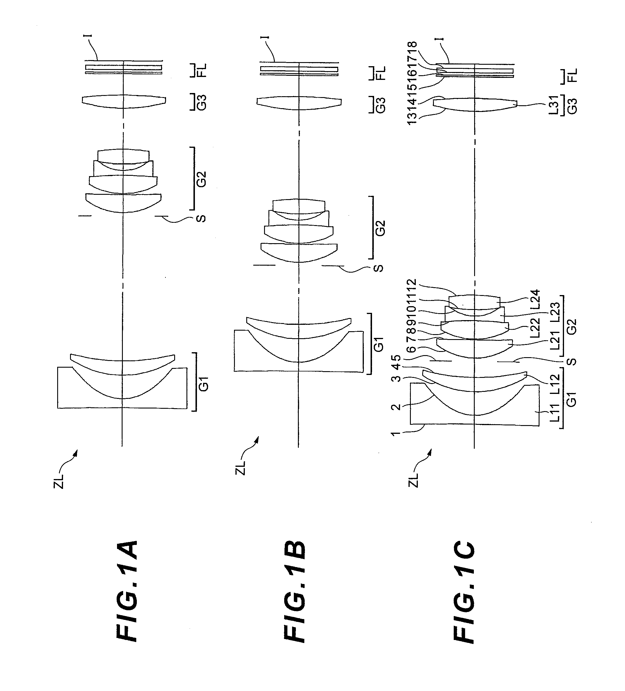
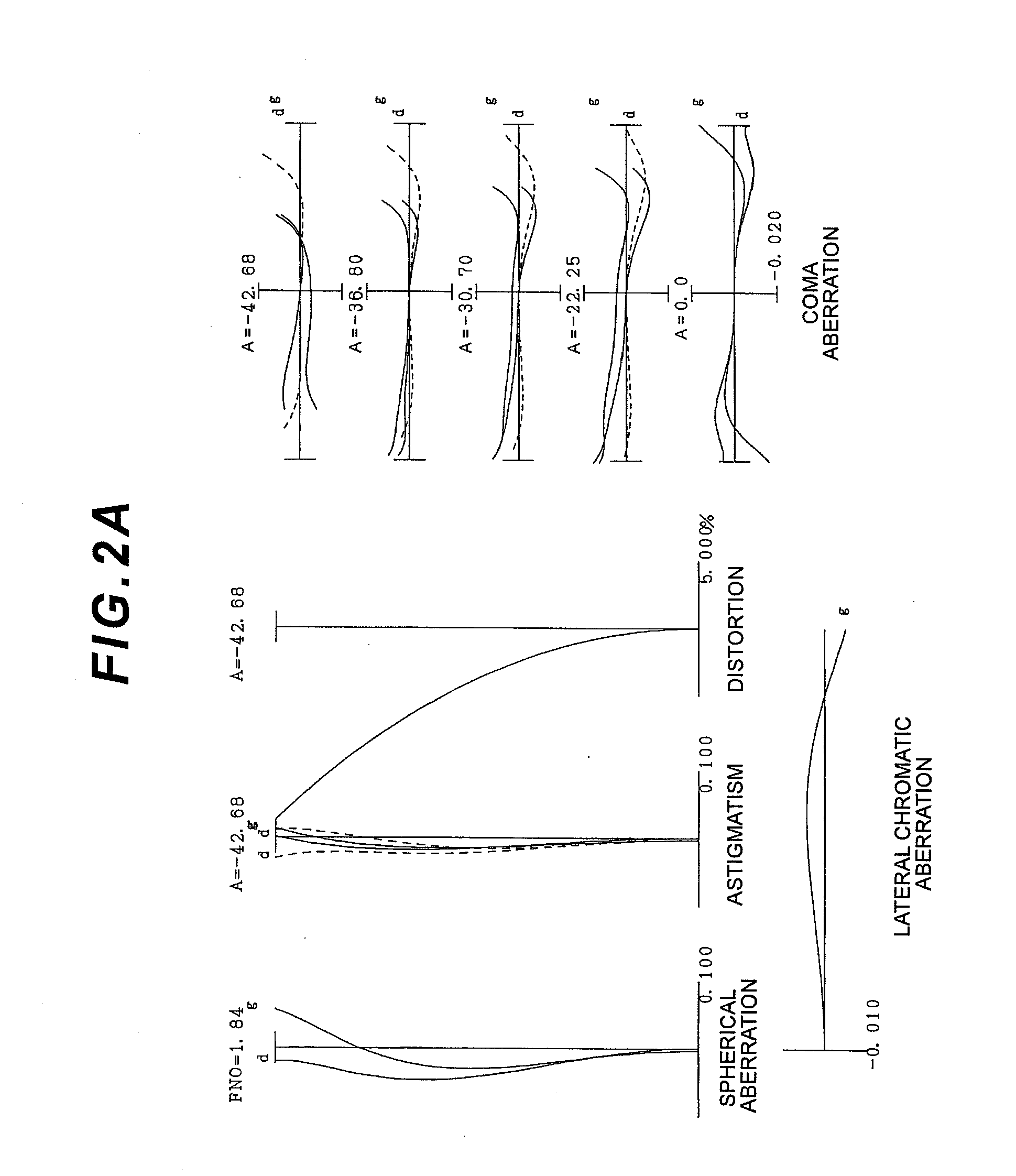
[0070]Each example of the present invention will now be described with reference to the drawings. Example 1 will be described with reference to FIG. 1, FIG. 2 and Table 1. FIG. 1A shows a lens configuration of the zoom lens according to Example 1 in the wide-angle end state, FIG. 1B shows the lens configuration in the intermediate focal length state, and FIG. 1C shows the lens configuration in the telephoto end state. The zoom lens ZL according to Example 1 comprises, in order from an object, a first lens group G1 having negative refractive power as a whole, a second lens group G2 having positive refractive power as a whole, and a third lens group G3 having positive refractive power as a whole. Upon zooming from the wide-angle end state to the telephoto end state, the first lens group G1 and the second lens group G2 move along the optical axis respectively, and the third lens group G3 is fixed on the optical axis, so that the distance between the first lens group G1 and the second l...

example 2

[0080]Example 2 will be described with reference to FIG. 3, FIG. 4 and Table 2. FIG. 3A shows a lens configuration of the zoom lens according to Example 2 in the wide-angle end state, FIG. 3B shows the lens configuration in the intermediate focal length state, and FIG. 3C shows the lens configuration in the telephoto end state. The zoom lens of Example 2 has a same configuration as the zoom lens of Example 1, except for a part of the shape of the first lens group G1, therefore each component the same as Example 1 is denoted with the same reference symbol, for which detailed description is omitted. The first lens group G1 in Example 2 includes, in order from an object, a negative meniscus lens L11 having a convex surface facing the object positive and a positive meniscus lens L12 having a convex surface facing the object, and the lens surface facing the image plane I in the negative meniscus lens L11 is aspherical.

[0081]Table 2 shows each data of Example 2. The surface numbers 1 to 1...

example 3

[0084]Example 3 will be described with reference to FIG. 5, FIG. 6 and Table 3. FIG. 5A shows a lens configuration of the zoom lens according to Example 3 in the wide-angle end state, FIG. 5B shows the lens configuration in the intermediate focal length state, and FIG. 5C shows the lens configuration in the telephoto end state. The zoom lens of Example 3 has a same configuration as the zoom lens of Example 1, except for a part of the shape of the second lens group G2, therefore each component the same as Example 1 is denoted with the same reference symbol, for which detailed description is omitted. The second lens group G2 in Example 2 includes, in order from an object, a first positive lens L21 having a biconvex positive lens, a second positive lens L22 having a biconvex positive lens, a biconcave negative lens L23, a third positive lens having a biconvex positive lens, and both surfaces of the first positive lens L21 are aspherical. Also, the second positive lens L22 and the negat...


PUM


Abstract

A zoom lens ZL having, in order from an object: a first lens group G1 having negative refractive power; a second lens group G2 having positive refractive power; and a third lens group G3 having positive refractive power, wherein, upon zooming from the wide-angle end state to the telephoto end state, at least the first lens group G1 and the second lens group G2 move along the optical axis so that the distance between the first lens group G1 and the second lens group G2 decreases, and the distance between the second lens group G2 and the third lens group G3 increases, the lens closest to the object in the second lens group G2 is a positive lens, and the object side lens surface of this positive lens is an aspherical surface of which radius of curvature increases in a direction from the optical axis to the periphery of the lens.

Description

RELATED APPLICATIONS[0001]This invention claims the benefit of Japanese Patent Applications Nos. 2011-013780 and 2012-007342 which are hereby incorporated by reference.TECHNICAL FIELD[0002]The present invention relates to a zoom lens and an optical apparatus, which are ideal for a digital still camera, and a method for manufacturing the zoom lens.TECHNICAL BACKGROUND[0003]In recent years, image capturing apparatuses (cameras) using solid-state image sensors, such as a digital still camera and a digital video camera, have rapidly progressed in terms of performance and compactness. For these image capturing apparatuses, a zoom lens is normally used for the image capturing lens. If a zoom lens is used, the user can easily take a picture at an angle of view which is optimum for the image capturing conditions. For the zoom lens, a wider angle of view, a larger aperture ratio and a higher zoom ratio are strongly demanded in order to expand the image capturing area of the camera. For this,...

Claims


Application Information

Patent Timeline
Patent Type & Authority Applications(United States)
IPC IPC(8): G02B15/14
CPCG02B15/177G02B13/18G02B15/143507
Inventor SHIMADA, TOSHIYUKI
Owner NIKON CORP
Why Eureka
Try Eureka