Image forming device and failure control system for the same

a technology of failure control system and image forming device, which is applied in the direction of electrographic process apparatus, instruments, optics, etc., can solve the problems of inconvenient user, damage to the device, and the entire device is always stopped, so as to secure the user's convenience

Inactive Publication Date: 2012-07-26
OKI DATA CORP
View PDF4 Cites 5 Cited by
  • Summary
  • Abstract
  • Description
  • Claims
  • Application Information

AI Technical Summary

Benefits of technology

[0006]The present application has an advantage to secure the user's convenience even when the unrecoverable failure occurs.

Problems solved by technology

In the applications, the “unrecoverable failure” means a failure that may be caused by heat generated by components and the like inside the device and that is difficult to overcome by the device itself, and that might damage the device.
However, in the above-described conventional technology, when the unrecoverable failure occurs, the entire device is always stopped because the power source that supplies power is turned off.
Therefore, there is a problem that it is inconvenient for the user, as the device cannot be used until the device has recovered from the failure.

Method used


Image

  • Image forming device and failure control system for the same
  • Image forming device and failure control system for the same
  • Image forming device and failure control system for the same

Examples


first embodiment

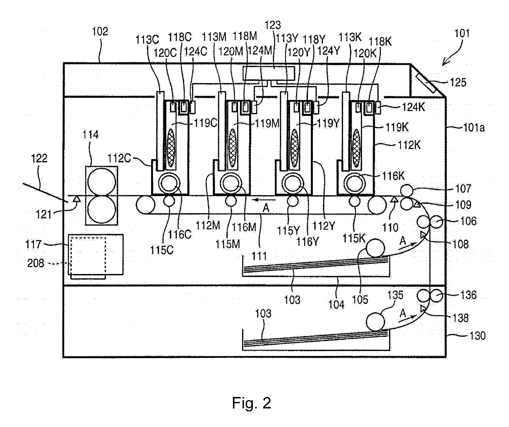
[0018]FIG. 2 is a schematic side cross-sectional view illustrating a configuration of the image forming device according to a first embodiment. In FIG. 2, reference numeral 101 is a printer as the image forming device. The explanation is made with an electrographic type color printer in the present embedment as an example. Reference numeral 102 is a top cover part that is mounted openablly and closably to an upper part of the printer 101. FIG. 2 is a left-side cross sectional view of the printer 101. The right side of the figure shows a front side 101a of the printer 101.

[0019]An image is printed on a recording medium 103 by the printer 101. The recording medium 103 is accommodated in a recording medium accommodation part 104 provided at a lower part of the printer 101. A sheet supply roller 105 is provided above the recording medium accommodation part 104. The sheet supply roller 105 separates and supplies, by rotation, each recording medium 103 accommodated in the recording medium...

second embodiment

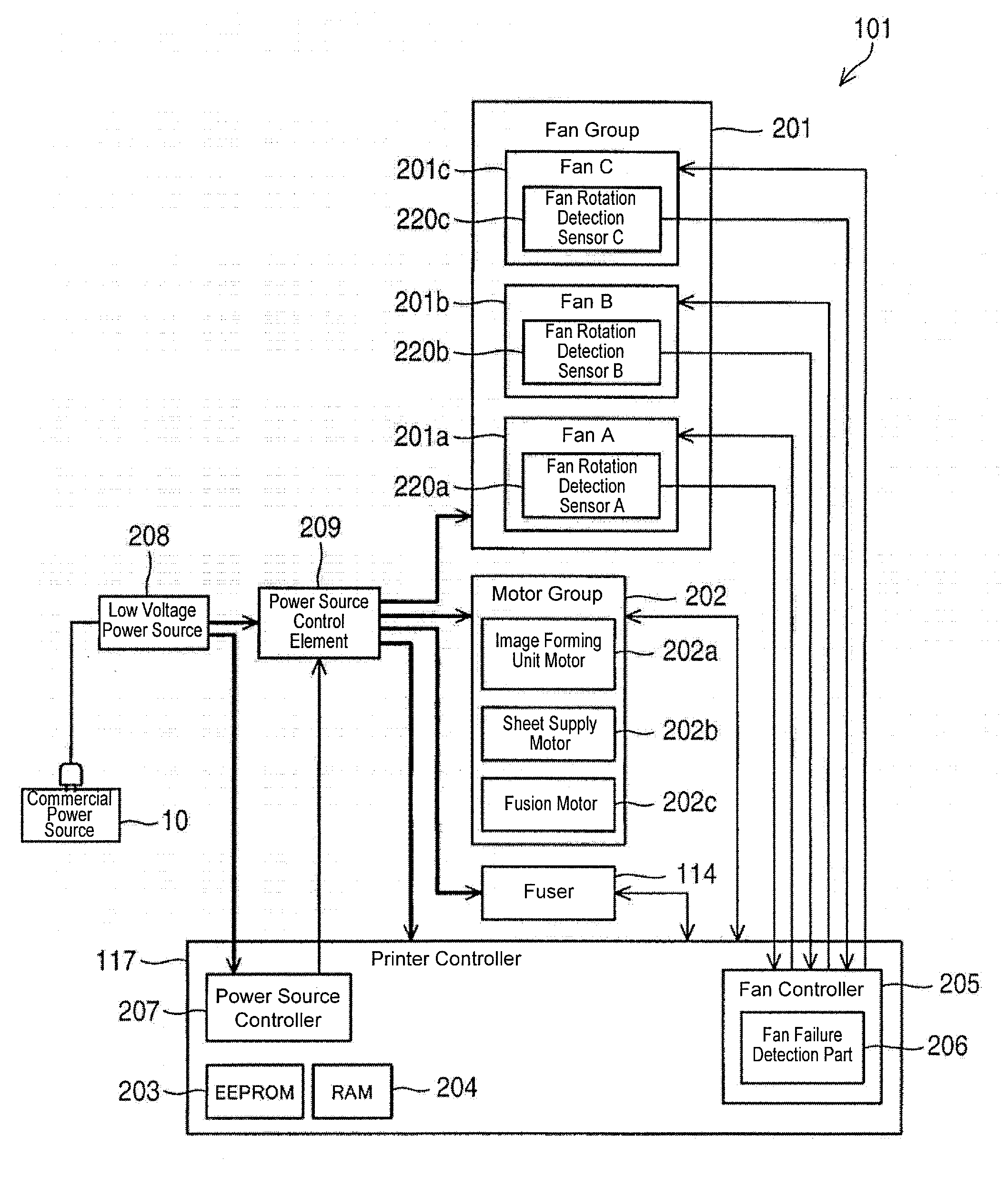
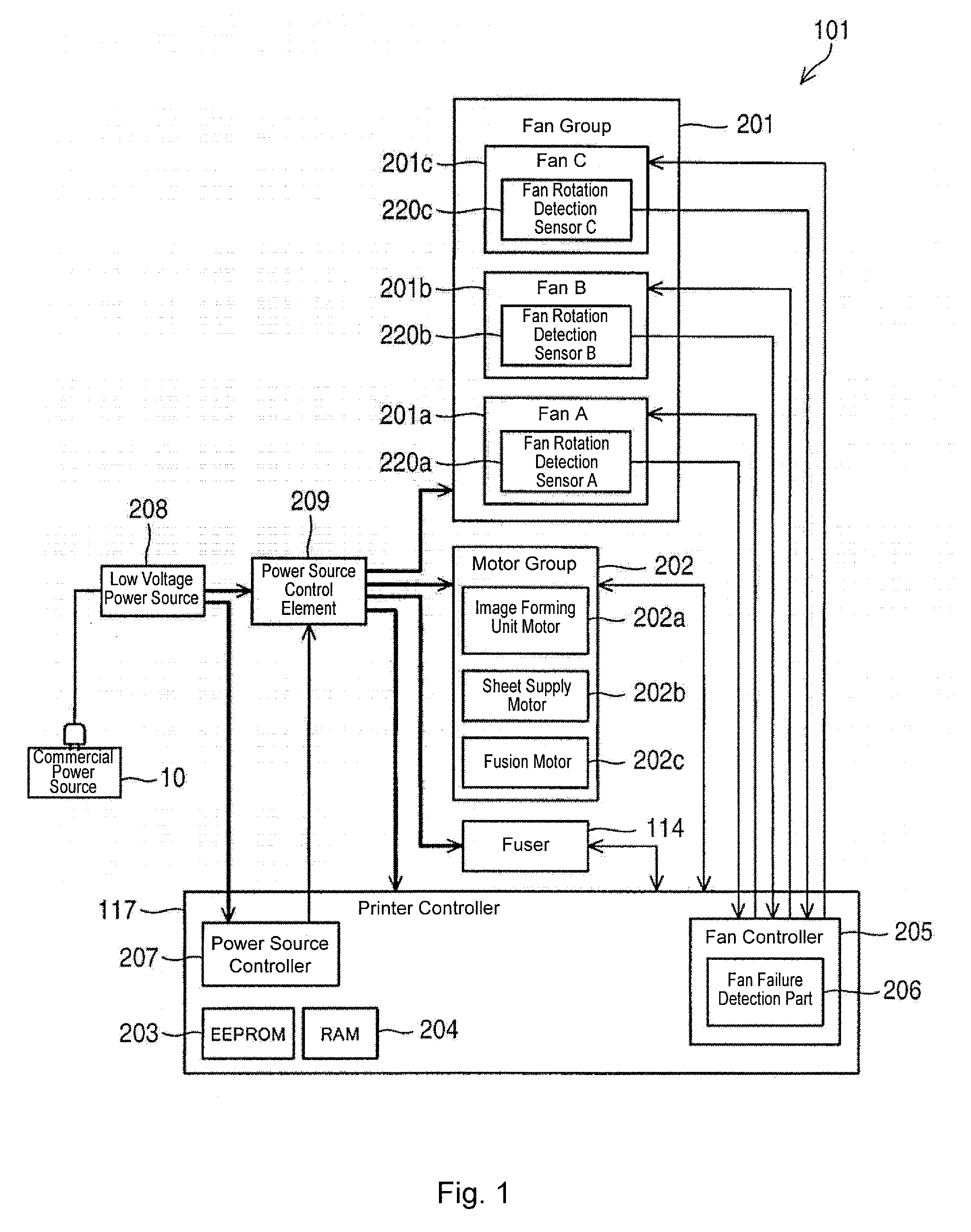
[0075]In contrast to the configuration of the first embodiment, a second embodiment has a configuration in which a duct that connects the cooling area of the fan A and the cooling area of the fan B and a shield plate between the duct and the cooling area of the fan B are provided. The configuration of the second embodiment is explained based on FIGS. 6A to 6D which are explanatory diagrams illustrating the mounting location and the cooling area of the fan according to the second embodiment, FIGS. 7A and 7B which are perspective views illustrating the mounting location and the cooling area of the fan according to the second embodiment, and FIG. 8 which is a block diagram illustrating the control configuration of the image forming device according to the second embodiment. Explanation of parts that are the same as those in the above-described first embodiment is omitted by applying the same symbols.

[0076]FIG. 6A is a cross-sectional view of the printer 101 from a left side surface. FI...


PUM


Abstract

An image forming device includes a plurality of power consumption parts that operate by power supply from a power source. The image forming device includes a failure detection part that detects occurrence of an unrecoverable failure, and a main controller that suppresses an amount of power supplied to the plurality of power consumption parts in response to detection by the failure detection part of the occurrence of an unrecoverable failure.

Description

CROSS REFERENCE TO RELATED APPLICATION[0001]The present application is related to, claims priority from and incorporates by reference Japanese patent application No. 2011-011328, filed on Jan. 21, 2011.TECHNICAL FIELD[0002]The present application relates to an image forming device, such as a printer, a photocopy machine, a facsimile machine, a multi-function peripheral (MFP) and the like, and relates to a failure control system for the above devices.BACKGROUND[0003]A conventional image forming device determines whether to turn on and off a power source device depending on the condition of a failure that has occurred in the device, and whether to turn off the power source that supplies power to the entire device when an unrecoverable failure occurs, in order to save unnecessary power consumption (see Japanese Laid-Open Patent Application No. 2010-147810 (paragraphs [0068]-[0076] and FIG. 2), for example). In the applications, the “unrecoverable failure” means a failure that may be ca...

Claims


Application Information

Patent Timeline
Patent Type & Authority Applications(United States)
IPC IPC(8): G03G15/00G03G21/20
CPCG03G2221/1645G03G15/5004G03G15/00
Inventor KUSHIMA, YASUTAKANAKAYAMA, AKIRA
Owner OKI DATA CORP
Why Eureka
Try Eureka