
Development device

Active Publication Date: 2012-07-26
CANON KK
View PDF4 Cites 0 Cited by
  • Summary
  • Abstract
  • Description
  • Claims
  • Application Information

AI Technical Summary

Benefits of technology

[0012]The present invention provides a development device that can effectively enhance the image density while suppressing the fog in the DC development method in which the development is performed using the DC bias.

Problems solved by technology

Therefore, a small number of toner particles can move under the development bias, and the amount of toner developed in the image bearing member is inevitably decreased to hardly obtain desired image density.
However, because a probability that the carrier adheres to an image region on the image bearing member is significantly increased, there is a limitation to the increase in image density by increasing the development bias.
However, in the technology of Japanese Patent Application Laid-Open No. 4-70874, the force moving the toner in the developer remains weak, and the electrode has only a small effect.

Method used


Image

  • Development device
  • Development device
  • Development device

Examples


first embodiment

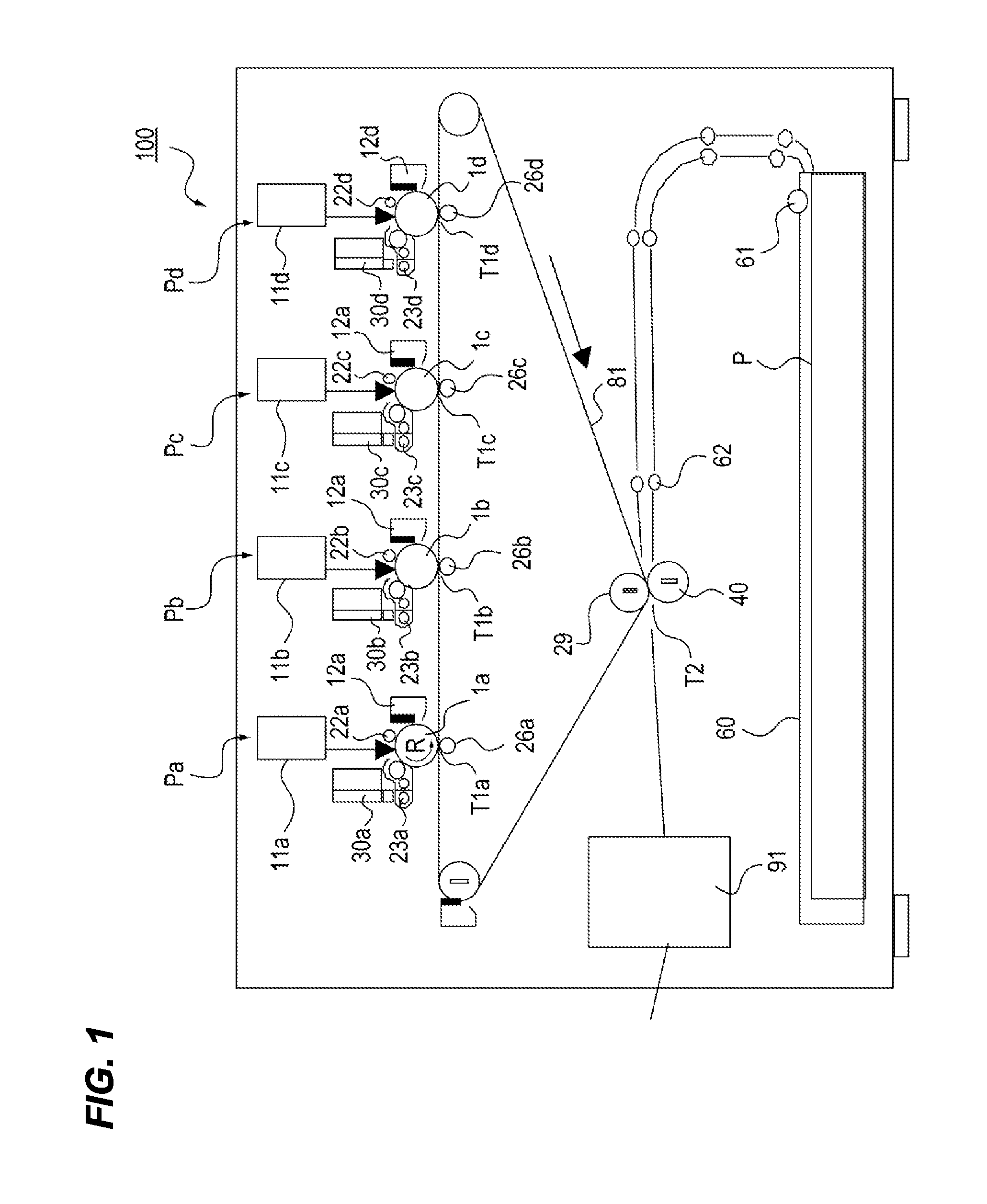
[0028]A development device and an image forming apparatus according to a first embodiment of the invention will be described with reference to the drawings. FIG. 1 is a configuration diagram of an image forming apparatus 100 of the first embodiment. As illustrated in FIG. 1, the image forming apparatus 100 of the first embodiment includes four image forming portions Pa, Pb, Pc, and Pd. Because the image forming portions Pa to Pd have the substantially same configuration, the image forming portion will be described by taking the image forming portion Pa as an example.

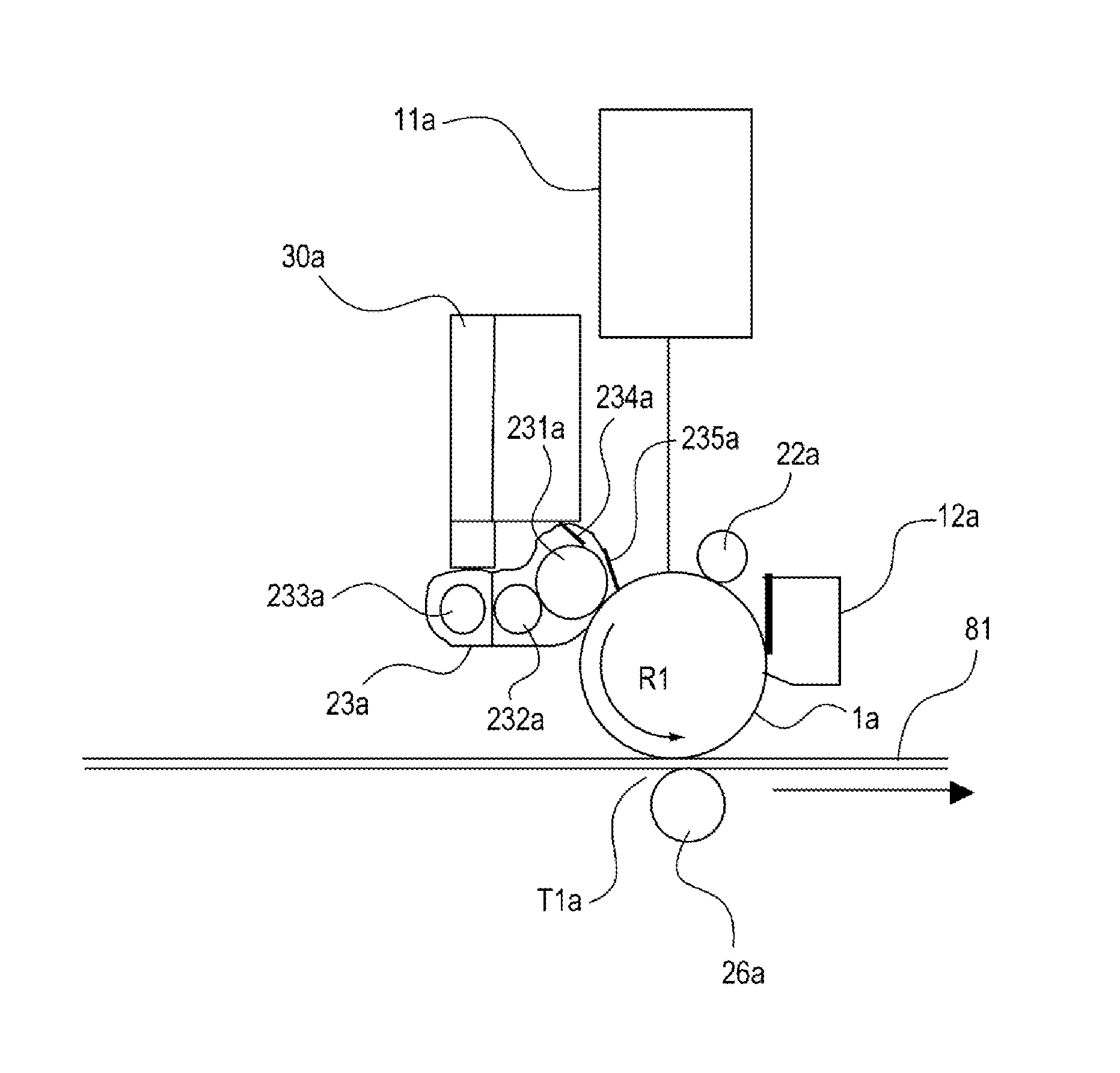
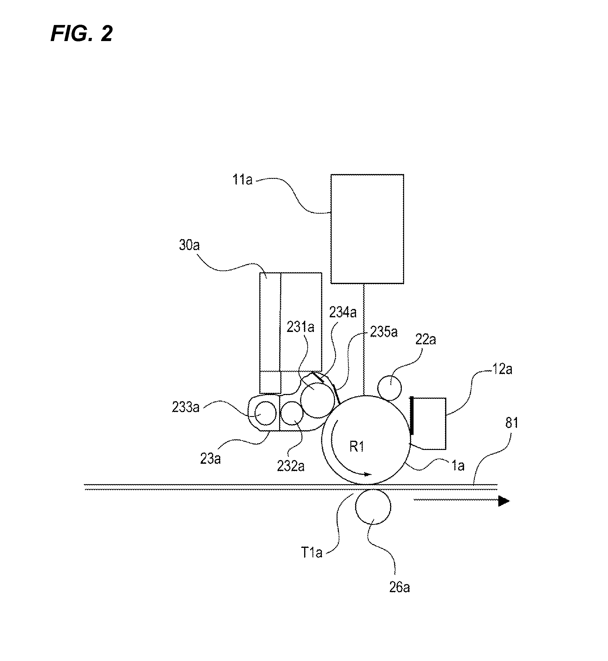
[0029]In the image forming portion Pa, a laser scanner 11a emits a laser beam according to an image signal of a yellow component color of an original, and an electrostatic latent image is formed on a photosensitive drum 1a (image bearing member) charged by a primary charger 22a. The electrostatic latent image is developed as a yellow toner image by a development device 23a. The yellow toner image is primary-transferred t...

second embodiment

[0069]A development device and an image forming apparatus according to a second embodiment of the invention will be described with reference to the drawings. The same component as the first embodiment is designated by the same numeral, and the description is not repeated. FIG. 12A is a view illustrating a state of a magnetic field line between the development sleeve 231a and the auxiliary electrode 235a when a magnetic plate 236b is not provided. FIG. 12B is a view illustrating the state of the magnetic field line between the development sleeve 231a and the auxiliary electrode 235a when the magnetic plate 236b is provided. FIG. 13 is a view illustrating the pre-bias dependence of the amount of toner put on the photosensitive drum and the amount of carrier adhering to the image region on the photosensitive drum when the magnetic plate 236b is placed and not placed.

[0070]As illustrated in FIG. 12B, in the image forming apparatus of the second embodiment, the magnetic plate 236b is att...


PUM


Abstract

A typical configuration of a development device and an image forming apparatus according to the invention includes: a development sleeve and an electrode portion. In the development device, a pre-bias is applied between the electrode portion and the photosensitive drum, a DC voltage is applied to the development sleeve, a development bias is applied between the development sleeve and the photosensitive drum, the toner in the developer on the development sleeve is moved to the photosensitive drum, and an electrostatic latent image is developed on the photosensitive drum. In the development device, electric field intensity between the electrode portion and the development sleeve by the pre-bias is larger than electric field intensity between the image bearing member and the development sleeve by the development bias.

Description

BACKGROUND OF THE INVENTION[0001]1. Field of the Invention[0002]The present invention is directed to an image forming apparatus, such as a copying machine and a printer, in which an electrophotographic system is utilized and a development device used in the image forming apparatus.[0003]2. Description of the Related Art[0004]In an electrophotographic image forming apparatus of the related art, charged toner is brought close to an image bearing member, and the toner is caused to adhere electrostatically to an electrostatic latent image on the image bearing member, thereby performing development to form an image. A two-component developer mainly containing non-magnetic toner and a magnetic carrier is widely used as a developer.[0005]A development bias that moves the developer to the image bearing member includes an AC development in which an AC voltage is superimposed on a DC voltage and a DC development in which only the DC voltage is utilized. While the AC development is excellent f...

Claims


Application Information

Patent Timeline
IPC IPC(8): G03G15/09
CPCG03G2215/0129G03G15/0813
Inventor OKUMURA, SHOHEI
Owner CANON KK
Features
  • Generate Ideas
  • Intellectual Property
  • Life Sciences
  • Materials
  • Tech Scout
  • Unparalleled Data Quality
  • Higher Quality Content
  • 60% Fewer Hallucinations
Learn More