Article storage facility

a technology for storage facilities and articles, applied in the direction of storage devices, loading/unloading, lifting devices, etc., can solve the problems of complex difficult to correct the position of articles or pick-up of articles, and difficult to perform each type of work with respect to the article storage unit, so as to facilitate work, facilitate the structure of the facility, and facilitate the effect of performing more easily

Active Publication Date: 2012-07-26
DAIFUKU CO LTD
View PDF2 Cites 27 Cited by
  • Summary
  • Abstract
  • Description
  • Claims
  • Application Information

AI Technical Summary

Benefits of technology

[0013]According to the first characteristic structure, the work frame is provided between the pair of front and rear vertical-movement guiding masts in a attachable or detachable manner, thereby the work frame can be attached thereto at a height corresponding to that of the article storage unit of the target articles to which the correction or pick-up work should be performed, because the pair of front and rear vertical-movement guiding masts of the stacker crane are arranged to lift and guide the platform to enable transfer of articles with respect to all of the plurality of article storage units being provided lengthwise and breadthwise. Therefore, an operator can perform the correction of the position of articles or pick-up of the articles, whilst riding on the work frame which thus makes the work easier. In addition, the work frame can be installed only when the correction or the pick-up work is necessary and can be uninstalled when it is not required. Therefore, the work frame would never interrupt the vertical movement of the platform. Thus, by the installation of the cab effectively utilizing the region for the vertical movement of the platform, the structure of the facility can be made simpler and the size of the travelling cart of the stacker crane in the front and rear direction thereof can be made smaller, compared to the facility disclosed in the Patent Publication 2, where the work frame is preset on the vertical-movement guiding masts.
[0014]According to the characteristic structure mentioned above, an article storage facility can be realized in which various types of work with respect to the article storage unit can be performed more easily and the workability of an operator with respect to the article storage unit is improved without incurring an increase in complexity and size of the structure.

Problems solved by technology

According to the facility disclosed in Patent Publication 1, an operator has to perform each type of work with respect to the article storage unit, such as the correction of the position of articles or pick-up of the articles, whilst situated on a ladder, which makes each type of works with respect to the article storage unit difficult.
Such a drawback becomes particularly marked when working with respect to articles located in a high place, in that, as such work has to be performed at a location which is high, the correction of the position of the articles or the pick-up of articles becomes very difficult.
However, the work frame has to be preset onto the vertical-movement guiding masts of the stacker crane, which makes the structure of the facility complex.
Therefore, the size of the stacker crane becomes large in the front-back width direction of the travelling cart, which incurs an increase in the size of the facility.

Method used


Image

  • Article storage facility
  • Article storage facility
  • Article storage facility

Examples


Embodiment Construction

[0033]An embodiment of the article storage facility according to the present invention will be explained, referring to the drawings.

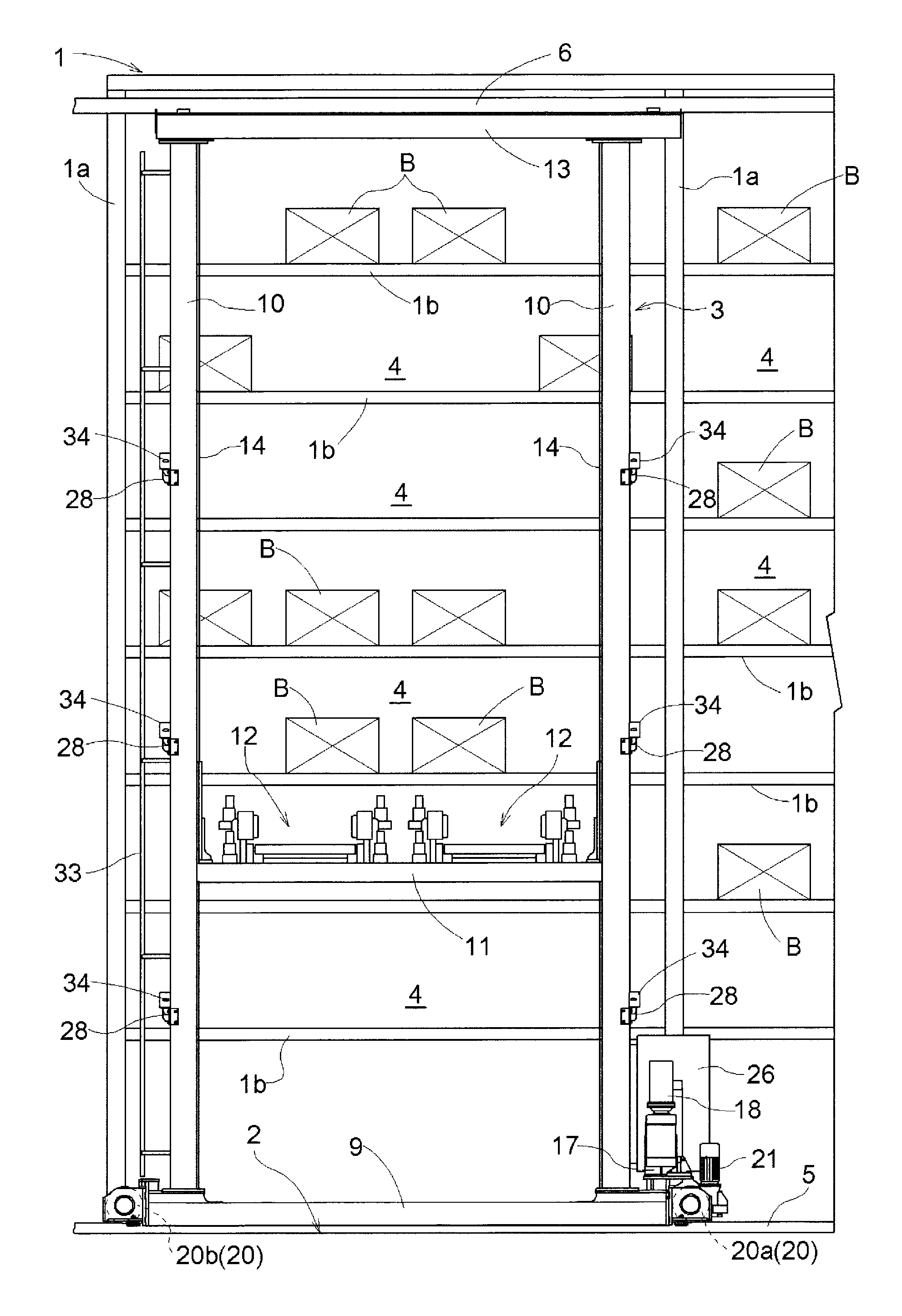
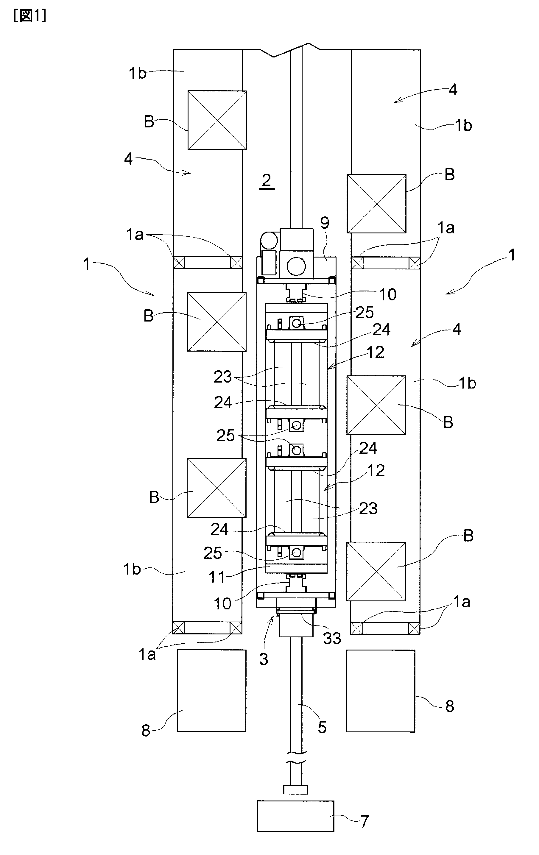
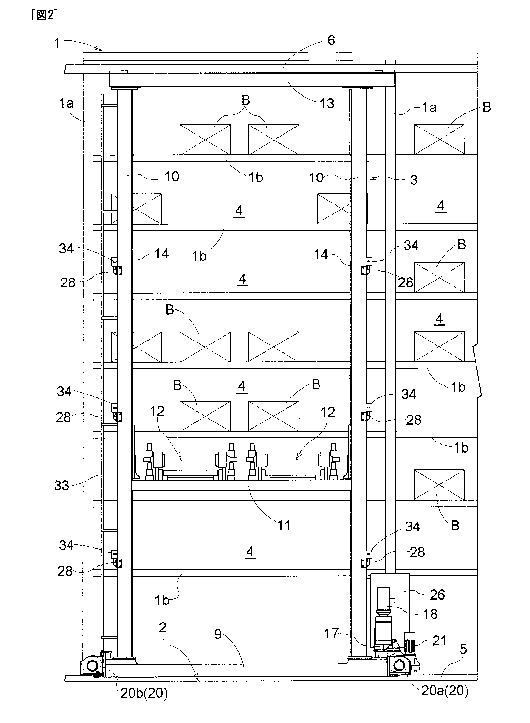
[0034]As shown in FIGS. 1 and 2, the article storage facility is comprised of two storing shelves 1 being arranged to be spaced from each other so that the fronts thereof, through which articles B are transferred in and out, face towards each other, and a stacker crane 3 which automatically travels along a travelling path 2 provided between the storing shelves 1.

[0035]Each of the storing shelves 1 comprises a plurality of rods 1a, which are stood in a sideways widthwise direction of the storing shelf (a vertical direction in FIG. 1 and a horizontal direction in FIG. 2) being spaced from each other, and an article mount plate 1b, which is arranged to be extended across the plurality of rods 1a provided in the sideways widthwise direction of the shelf. The storing shelves 1 are arranged so as to store articles B in a manner that the articles B are mounted...


PUM


Abstract

An article storage facility with a storing shelf structured by lining up a plurality of article storage units in the vertical direction and the horizontal direction. A stacker crane travels along a traveling rail to transport articles to each article storage unit. The stacker crane has a traveling cart having a pair of vertical-movement guiding masts set upright on both ends of the traveling cart in the front-back width direction, and a vertical-movement platform movable vertically along the pair of vertical-movement guiding masts between the pair of vertical-movement guiding masts. An article transfer device is provided on the vertical-movement platform. The stacker crane has a work frame, having a width in the sideways direction of the traveling cart and the front-back width direction of the traveling cart between the pair of vertical-movement guiding masts structured so as to be freely attached and removed.

Description

TECHNICAL FIELD[0001]The present invention relates to an article storage facility comprising storing shelves composed of a plurality of article storage units lengthwise and breadthwise, a stacker crane arranged to be runnable along travelling rails provided at the front side of the storing shelves along the sideways widthwise direction of the storing shelves to transfer articles to each of the article storage units, and a crane control means for controlling the actuation of the stacker crane; where said stacker crane comprises a travelling cart runnable along the travelling rails, a pair of front and rear vertical-movement guiding masts being stood from the travelling cart with a space in the front-back width direction of the travelling cart, a platform being guided and supported by the pair of front and rear vertical-movement guiding masts between the pair of front and rear vertical-movement guiding masts, and an article transfer device being provided on the platform.BACKGROUND OF ...

Claims


Application Information

Patent Timeline
Patent Type & Authority Applications(United States)
IPC IPC(8): B65G1/137
CPCB66F9/07B65G1/0407
Inventor YOSHINAGA, KAZUHARU
Owner DAIFUKU CO LTD
Why Eureka
Try Eureka