Plug receptacle

a plug receptacle and plug pin technology, applied in the direction of two-pole connection, electrical discharge lamp, coupling device connection, etc., can solve the problems of reducing the dielectric strength of the plug pin, power loss, and cumbersome and laborious task of plug insertion into the outlet unit b>110/b>, so as to prevent the reverse insertion, easy to recognize the orientation of the plug, and easy to perform position alignment

Inactive Publication Date: 2012-07-26
PANASONIC CORP
View PDF11 Cites 25 Cited by
  • Summary
  • Abstract
  • Description
  • Claims
  • Application Information

AI Technical Summary

Benefits of technology

[0030]In accordance with embodiments of the present invention, the outlet unit includes the plug-receiving portion having the substantially quadrangular-shape viewed from the front, the periphery of which is surrounded by the insertion groove. In the plug-receiving portion, two pin-inserting holes corresponding to the pin-receiving pieces for supplying the DC power are arranged along one side of the plug-receiving portion serving as the reference side and offset closer to the reference side of the plug-receiving portion. Accordingly, it is possible to easily recognize an orientation of the plug to be inserted into the outlet unit. In addition, since the orientation of the plug to be inserted into the outlet unit is restricted by the substantially quadrangular-shaped surrounding wall of the plug to be inserted into the insertion groove provided around the substantially quadrangular-shaped plug-receiving portion, it is possible to embody the DC outlet capable of easily performing position alignment, preventing the reverse insertion, and being conveniently used. Further, the plug-receiving portion has the substantially quadrangular-shape. Accordingly, even when two pin-inserting holes are arranged offset closer to the reference side, it is possible to obtain a sufficient insulation distance without reducing the distance between the pin-inserting holes, to thereby prevent the DC outlet from being scaled up.

Problems solved by technology

Power loss occurs when the AC-DC converter converts the AC power to the DC power.
Thus, the task of inserting the plug 100 into the outlet unit 110 becomes cumbersome and onerous.
This poses a problem of reducing the dielectric strength of the plug pins.
However, there is posed a problem in that the increase in the size of the plug-receiving portion 302 results in an increase in the size of the outlet unit 300.

Method used


Image

  • Plug receptacle
  • Plug receptacle
  • Plug receptacle

Examples


first embodiment

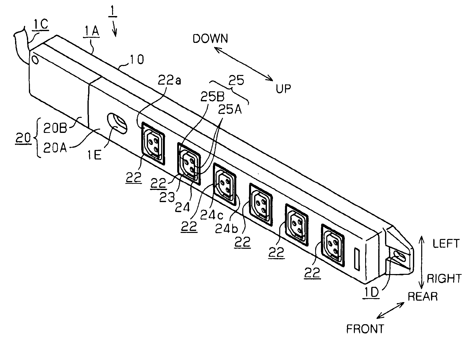
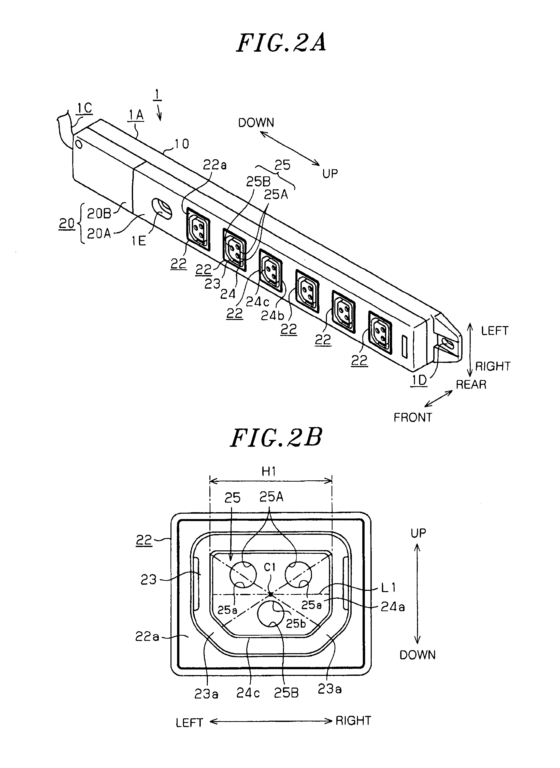
[0055]There will be described a plug receptacle in accordance with a first embodiment of the present invention which is embodied as an outlet attached to an information rack for accommodating a server device or the like with reference to FIGS. 1 to 11.

[0056]First of all, the relation between an information rack JR and a plug receptacle 1 and a power supply structure of the plug receptacle 1 will be described with reference to FIG. 1. In FIGS. 3 to 11, a cable 1C of the plug receptacle 1 is omitted, and a plug 2 is omitted in FIG. 2.

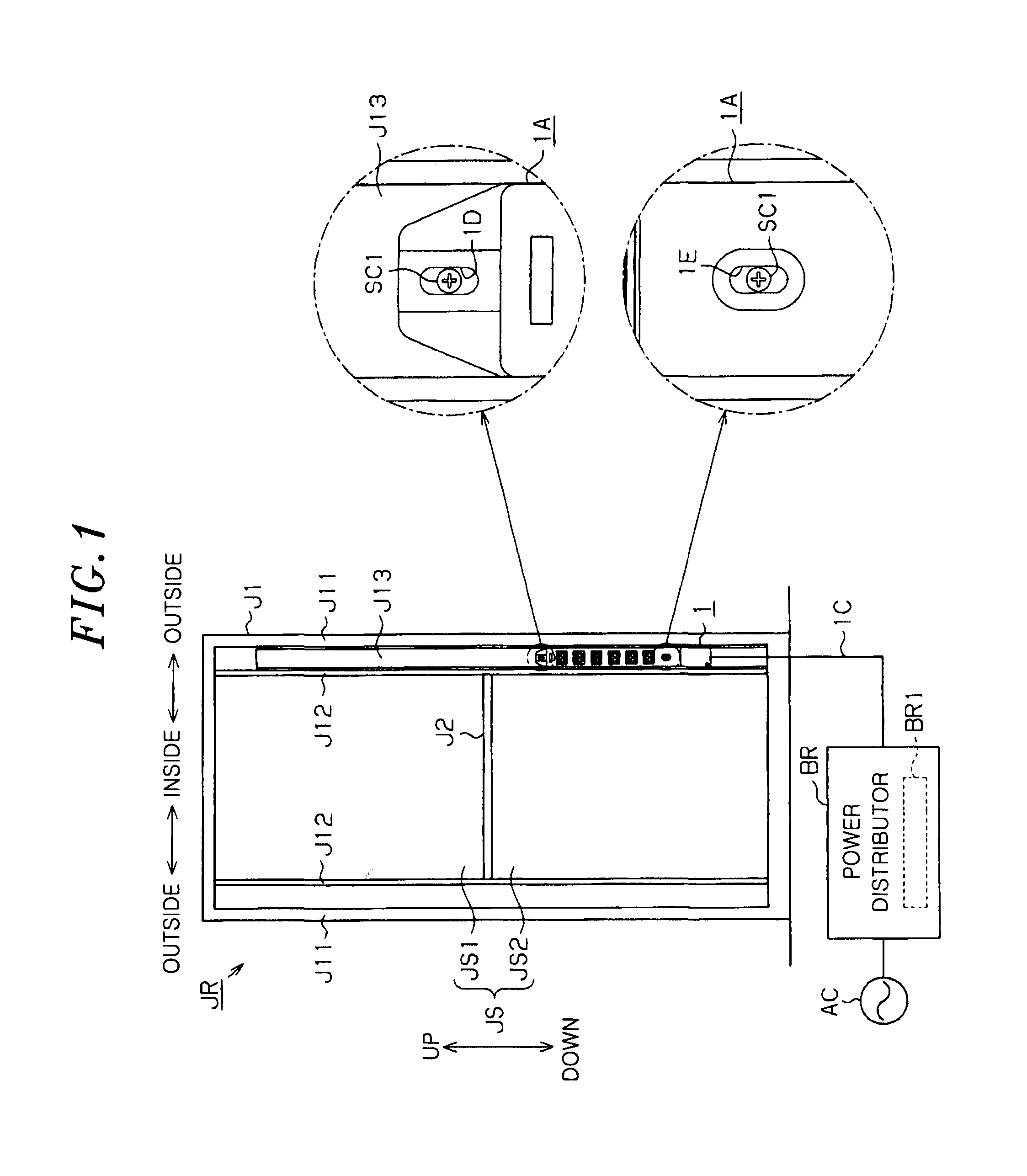
[0057]As shown in FIG. 1, the information rack JR is formed in a box shape by a frame body J1 forming an outer frame thereof. The information rack JR includes an accommodating section JS having an open front portion and serving as a space for accommodating a server device (not shown). Further, the information rack JR includes a partition member J2 for partitioning the accommodating section JS into an upper accommodating section JS1 and a lower accommodati...

second embodiment

[0153]A second embodiment in which a plug receptacle of the present invention is embodied as a table tap connected to a DC outlet buried in a wall of a building will be described with reference to FIGS. 12 to 15. FIG. 15 omits illustration of the cable and the plug.

[0154]The entire DC power distribution system 70 installed at a house H will be described with reference to FIG. 12.

[0155]As shown in FIG. 12, the house H is provided with a DC power supply unit 71 for outputting a DC power; and an electric device 72 operating at a DC power. The DC power is supplied to the electric device 72 through DC power supply lines Wdc connected to an output terminal of the DC power supply unit 71.

[0156]Moreover, DC breakers 73 are provided between the DC power supply unit 71 and the electric device 72. The DC breakers 73 monitor a current flowing in the DC power supply lines Wdc and restrict or interrupt, when an error is detected, DC power supply from the DC power supply unit 71 to the electric de...


PUM


Abstract

A plug receptacle includes a housing having at least one outlet unit to which a plug is adapted to be connected to supply a DC power to the plug, and a cable, connected to the housing, for supplying the DC power to the housing. The outlet unit includes a plug-receiving portion having a plurality of substantially circular pin-inserting holes into which plug pins of the plug are inserted and an insertion groove formed to surround a periphery of the plug-receiving portion. The plug-receiving portion has a substantially quadrangular shape viewed from a front side thereof. The insertion groove is adapted to receive a surrounding wall of the plug and has a substantially quadrangular shape viewed from the front side. The pin-receiving holes are arranged along one side of the plug-receiving portion serving as a reference side and offset closer to the reference side than an opposite side to the reference side.

Description

FIELD OF THE INVENTION[0001]The present invention relates to a plug receptacle to which a plug is adapted to be connected, and including a housing having an outlet unit for supplying DC power to the plug and a cable connected to the housing.BACKGROUND OF THE INVENTION[0002]Conventionally, there has been known a plug receptacle having an outlet unit to which a plug of an electric device such as a personal computer or a phone is detachably connected to and serving to supply an operation power (AC power) to the electric device through the plug, e.g., table tap (see, e.g., Japanese Patent Application Publication No. H07-211384 (JP07-211384A)).[0003]In the meantime, most of electric devices make use of direct current (DC) power as their drive power. For that reason, the alternating current (AC) power supplied from an AC outlet is converted to DC power by an AC-DC converter and then fed to the electric devices. Power loss occurs when the AC-DC converter converts the AC power to the DC pow...

Claims


Application Information

Patent Timeline
Patent Type & Authority Applications(United States)
IPC IPC(8): H01R24/00H01R29/00
CPCH01R13/64H01R2103/00H01R25/003H01R24/76
Inventor BESSYO, KEISUKEHIGASHIDE, KOUJIKAWAMOTO, TAKASHITAKII, TOSHIYUKI
Owner PANASONIC CORP
Why Eureka
Try Eureka