
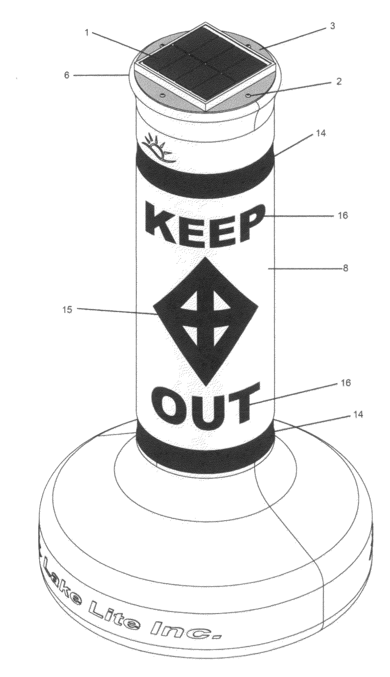
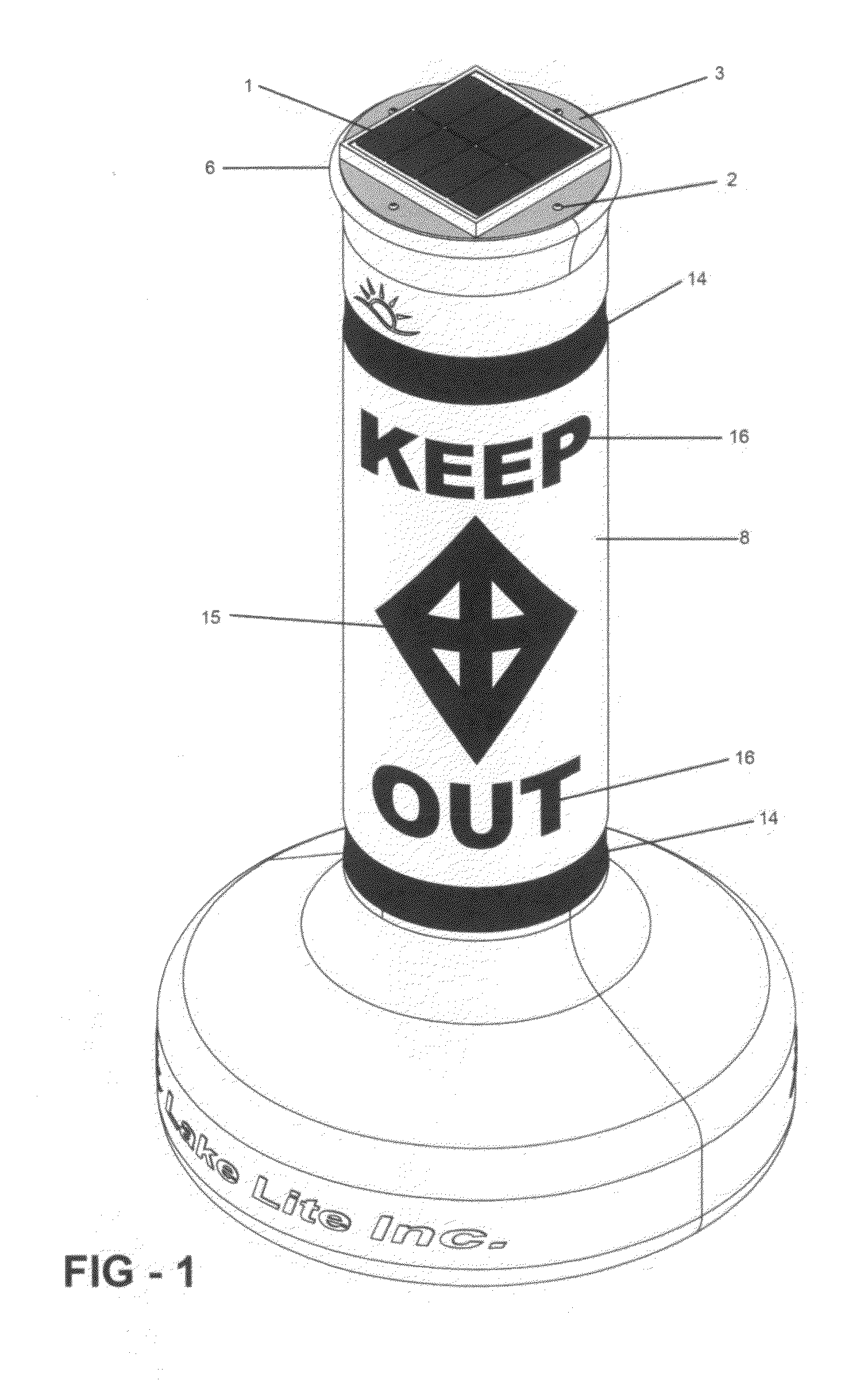
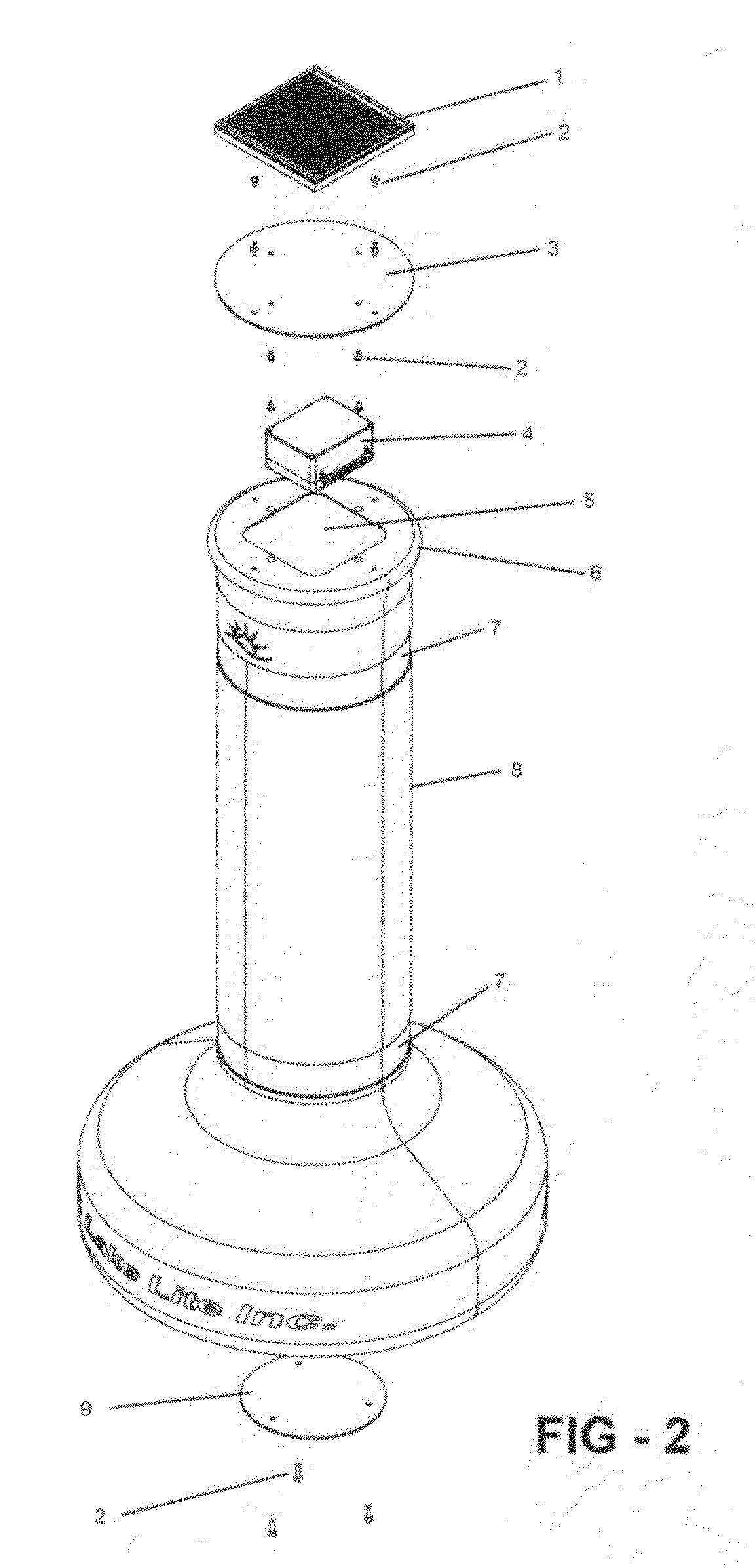
Silhouette illuminating solar powered regulatory buoy

a solar-powered, buoy-based technology, applied in waterborne vessels, special-purpose vessels, energy supply, etc., can solve the problems of reducing the visibility of reflective materials, affecting the safety of passengers, bird droppings, etc., to prevent vessel-buoy collisions, easy to read by nighttime boaters, and easy to identify at night

Inactive Publication Date: 2012-07-26
MARTZALL JEFFREY SCOTT
View PDF4 Cites 5 Cited by
  • Summary
  • Abstract
  • Description
  • Claims
  • Application Information

AI Technical Summary

Benefits of technology

[0013]The primary objective of the invention is to provide a highly visible buoy which conveys a visible and legible message to boaters at both day and night.
[0014]Another object of the invention is to provide a lighted buoy that provides a silhouette or lighted view of the buoys message and symbol content so that it is easily readable by nighttime boaters.
[0015]Another object of the invention is to provide a lighted buoy that boaters can easily identify at night to prevent vessel-buoy collisions.
[0016]Another object of the invention is to provide a lighted buoy with reflective material in which the buoy can be visible at night under reflected light even if the light source is rendered off.
[0017]Another object of the invention is to provide a lighted buoy where attached messages and symbols placed on the buoy body create a silhouette or lighted view of the message and symbol content.
[0018]Another object of the invention is to provide an easily serviceable self contained solar lighting unit which provides illumination to the buoy.

Problems solved by technology

Buoys that rely on reflective materials to be visible at night have several problems.
All of these factors reduce the reflective materials visibility.
This is problematic as many nighttime vessels do not use headlights.
Buoys and boats move with wave action, which means the angle at which light is directed and reflected may not result in visibility at all times.
Lighting elements and or beacons are typically affixed to the tops of buoys and therefore are easily damaged or rendered less effective from bird droppings, debris, abrasion, and collision.
Signaling lights or beacons are also added to the tops of buoys which blink in accordance with maritime flash codes, however, boaters not familiar with maritime flash codes may not understand the important message the buoy is intended to convey.
Phosphorescent pigments are problematic for using on buoys as they are very dim and do not provide visibility at far distances or for prolonged periods of time.
Phosphorescent pigments dim rapidly shortly after dark and do not provide the full lighting effect through the duration of the night.
If there is an overcast or cloudy day the phosphorescent pigments will not absorb enough sunlight and will result in short illumination times. In addition portions of the buoy which are face down in the water will not absorb sunlight during the day and thus as the buoy rotates at night, it may expose an area that does not illuminate.
In general, fluorescent materials at maximum have low luminance and short light emission times. For this reason, phosphorescent or luminescent materials are not typically bright enough or long lasting enough to provide effective means for lighting buoys.
Furthermore the general lighting direction is upward and it may be difficult for boaters at distances to view the buoy from the side.
This design incorporates a translucent lens body which makes the buoy more difficult to see as it will visually blend in with the water or background.
Furthermore, this buoy only conveys light flashing or signaling messages.

Method used


Image

  • Silhouette illuminating solar powered regulatory buoy
  • Silhouette illuminating solar powered regulatory buoy
  • Silhouette illuminating solar powered regulatory buoy

Examples


Embodiment Construction

[0034]Detailed descriptions of the preferred embodiment are provided herein. It is to be understood, however, that the present invention may be embodied in various forms. Therefore, specific details disclosed herein are not to be interpreted as limiting, but rather as a basis for the claims and as a representative basis for teaching one skilled in the art to employ the present invention in virtually any appropriately detailed system, structure or manner.

This is the Detailed Description of the Unit

[0035]A silhouette illuminating solar powered buoy comprising of a durable rotationally molded buoy body capable of withstanding mooring forces and boat collisions. The silhouette illuminating solar powered buoy has a separate yet integrated solar powered lighting unit which illuminates the body of the buoy making it visible at night. Reflective sticker bands, symbols, and messages may be placed on the buoy body to create a highly visible silhouette image of those stickers when the buoy ill...


PUM


Abstract

A silhouette illuminating solar powered buoy with a protected illumination source such as a solar lighting unit. The buoy body can be shaped, colored, and formed to various and or necessary buoy standards or regulations. The buoy body has an accessible opening to allow the solar lighting unit to be placed in a manor which allows it to internally illuminate the buoy body. Reflective sticker messages and symbols may be placed on the buoy to convey important information to boaters. When the illumination source is turned on at night, the stickers block the emitting light projected from the buoy body, and thus create a highly visible and legible silhouette image of the message and symbol content. The illuminating buoy and silhouette image of the message and symbol content makes the buoy easily visible at night from all angles and thus adds to the safety of person and watercraft operating at night.

Description

CROSS REFERENCE TO RELATED APPLICATIONS [0001]Not ApplicableFEDERALLY SPONSORED RESEARCH OR DEVELOPMENT [0002]Not ApplicableDESCRIPTION OF THE ATTACHED APPENDIX [0003]Not ApplicableBACKGROUND OF THE INVENTION[0004]1. Field of Invention[0005]This invention relates generally to the field of marine navigational and regulatory markers and more specifically to a regulatory buoy with the ability to illuminate and display the contents of its message at night. Regulatory and marker buoys are used to inform boaters of important information. Much like a road sign conveys important information on our highways; regulatory buoys provide important information to boaters on our waterways. Some common messages may read “Danger Shallow Rocks”, “Slow No Wake”, “Swim Area”, or “Marina Entrance”; however, there are hundreds of messages that can be displayed. These messages are also accompanied by different symbols which provide detailed and important information to boaters. Buoys provide boaters inform...

Claims


Application Information

Patent Timeline
Patent Type & Authority Applications(United States)
IPC IPC(8): B63B22/16B63B45/00
CPCB63B22/166B63B2209/18B63B2201/12B63B2201/08
Inventor MARTZALL, JEFFREY SCOTT
Owner MARTZALL JEFFREY SCOTT
Learn More