Telescopic gun sight with linear optical adjustment mechanism

a linear, optical adjustment technology, applied in the field of optical gun sights, can solve the problems of limited amount of reticle adjustment, limited amount of titling tube mechanism, and inability to use a small diameter inner tube,

Active Publication Date: 2012-08-02
LUCIDA RES
View PDF8 Cites 11 Cited by
  • Summary
  • Abstract
  • Description
  • Claims
  • Application Information

AI Technical Summary

Benefits of technology

[0017]In accordance with one embodiment, this invention introduces a telescopic gun sight comprising an objective lens, a reticle, an image erecting means, an eyepiece lens, an...

Problems solved by technology

A first drawback is that the possible amount of reticle adjustment is limited to the clearance between the inner tube and the scope's main tube.
Furthermore, optical considerations make using a small diameter inner tube impractical.
Therefore, the titling tube mechanism is naturally limited in terms of the amount of elevation and windage adjustments possible.
A second drawback is that due to the circular shape of the inner tube and the scope's main tube, vertical and horizontal movements of the inner tube interfere with each other near the ends of the adjustment rang...

Method used


Image

  • Telescopic gun sight with linear optical adjustment mechanism
  • Telescopic gun sight with linear optical adjustment mechanism
  • Telescopic gun sight with linear optical adjustment mechanism

Examples


first embodiment

A. First Embodiment of the Invention

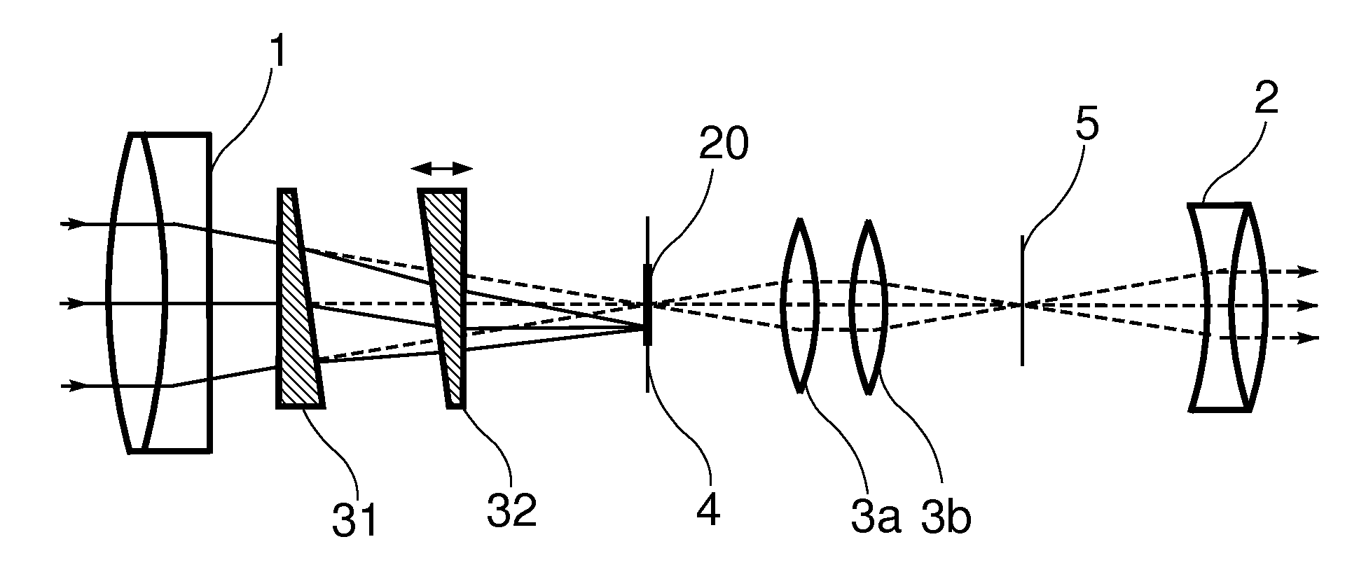
[0028]A first embodiment of the invention is shown in FIG. 4. In this embodiment a telescopic sight includes an objective lens 1 which forms a first image of the target on the objective focal plane 4. A reticle 20 is placed at the objective focal plane. The first image produced by the objective lens is upside down and laterally reversed. A pair of convex lenses 3a and 3b relay this first image to the eyepiece focal plane 5 and form a second, upright and laterally correct image there. The eyepiece 2 takes this second image and produces a virtual magnified image for the shooter to see.

[0029]Two thin prisms 31 and 32 are placed after the objective lens 1 and before objective focal plane 4. One of these prisms is mounted upside down such that its base faces the apex of the other prism. Furthermore, the prisms are mounted such that at least one prism can move along the optical axis of the objective. (In FIG. 4, prism 32 is designated as the movable pri...

second embodiment

B. Second Embodiment of the Invention

[0032]A second embodiment of the invention is shown in FIG. 5. In this embodiment the pair of prisms 31 and 32 are placed after the objective focal plane 4 and before the erecting lenses 3a and 3b. The reticle 20 is placed at the eyepiece focal plane 5. Other than these changes, the arrangement of elements is similar to the first embodiment.

[0033]To adjust the point of aim, one of the prisms 31 and 32 is moved forward or backward along the optical axis of the sight. This will cause the real image produced by the relay lenses 3a and 3b to shift upward and downward on the eyepiece focal plane 5. Since the reticle 20 is mounted coplanar with the eyepiece focal plane 5, the target image shifts on the reticle and an adjustment for point of aim is provided.

third embodiment

C. Third Embodiment of the Invention

[0034]A third embodiment of the invention is shown in FIG. 6. The arrangement of elements in this embodiment is similar to the second embodiment above except that the pair of prisms 31 and 32 are placed after the erecting lenses 3a and 3b and before the eyepiece focal plane 5. The reticle 20 is placed at the eyepiece focal plane 5.

[0035]The operation of this embodiment is similar to the second embodiment: To adjust the point of aim, one of the prisms 31 and 32 is moved forward or backward along the optical axis of the sight. This will cause the real image produced by the relay lenses 3a and 3b to shift upward and downward on the eyepiece focal plane 5. Since the reticle 20 is mounted coplanar with the eyepiece focal plane 5, the target image shifts with respect to the reticle and the sight's point of aim is adjusted.

D. Advantages

[0036]Based on the above descriptions of some embodiments of the invention, a number of advantages of one or more aspect...


PUM


Abstract

One embodiment of the invention describes a telescopic gun sight comprising an objective lens, a reticle, an image erecting means, an eyepiece lens, and a pair of prisms, wherein said pair of prisms are positioned between said objective lens and said reticle so that changing the linear separation between the prisms adjusts the point of aim. Other embodiments are described and shown.

Description

I. CROSS-REFERENCE TO RELATED APPLICATIONS[0001]Not ApplicableII. FEDERALLY SPONSORED RESEARCH[0002]Not ApplicableIII. SEQUENCE LISTING OR PROGRAM[0003]Not ApplicableIV. FIELD OF THE INVENTION[0004]This application relates to optical gun sights, specifically to an improved method of adjusting the point of aim in telescopic gun sights.V. BACKGROUND OF THE INVENTION[0005]A telescopic gun sight, commonly called a rifle scope, is a device used to provide an accurate point of aim for firearms such as rifles, handguns and shotguns. It is used with other types of weapons such as bows and crossbows as well. A telescopic sight can dramatically improve the functionality of a firearm by providing the shooter with a simple yet highly accurate means for aiming at distant targets.[0006]A simplified schematic diagram of a modern telescopic sight is shown in FIG. 1. With reference to this figure, a telescopic sight uses an objective lens or lens group 1 to form a real image of the target at the obj...

Claims


Application Information

Patent Timeline
IPC IPC(8): F41G1/38G02B23/00
CPCF41G1/38G02B27/648G02B23/14G02B23/02
Inventor JAHROMI, OMID
Owner LUCIDA RES
Why Eureka
Try Eureka