
Vented Armor V Structure

a technology of armor and v structure, applied in the field of vented armor v structure, can solve the problems of preventing the valve from functioning properly and adding weight to the vehicle, and achieve the effect of reducing potential overheating

Inactive Publication Date: 2012-08-02
UNITED STATES OF AMERICA THE AS REPRESENTED BY THE SEC OF THE ARMY
View PDF7 Cites 11 Cited by
  • Summary
  • Abstract
  • Description
  • Claims
  • Application Information

AI Technical Summary

Benefits of technology

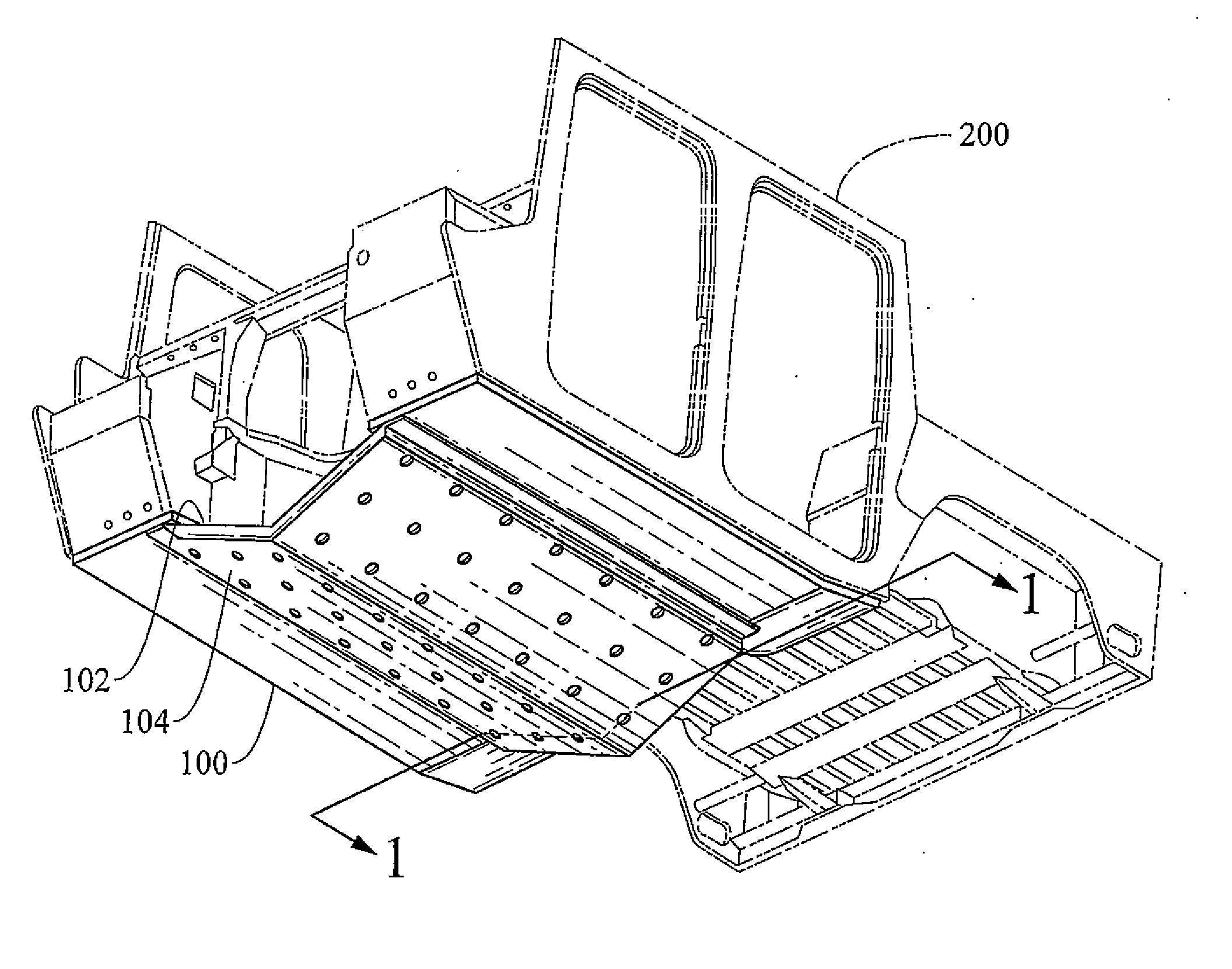
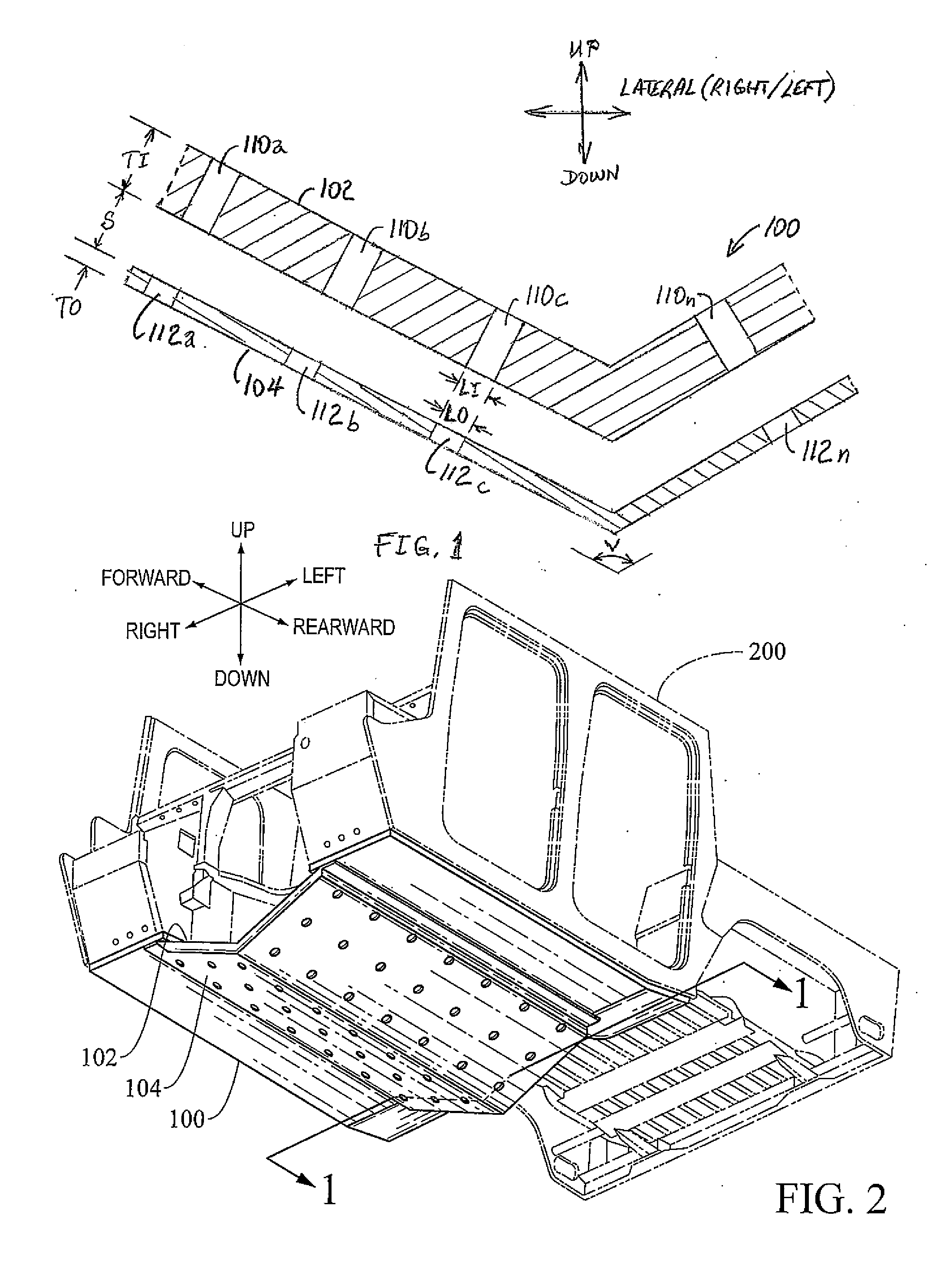
[0008]In accordance with the present invention, to mitigate potential overheating a “vented”“V” underbody vehicle armor structure can be implemented which allows air to flow through the “V” during normal operation while providing protection from underbody blast events. The “V” armor generally comprises two layers of armor structure that are spaced apart: a thick inner “V” structure element intended to withstand the blast loads, and a thin outer “V” structure element intended to collapse during a blast. Both inner and outer structures may be perforated, with openings in corresponding locations such that a passageway might be easily constructed from the inner to the outer structural layers of armor.
[0009]To reduce or prevent accumulation of debris in the space between the layers, a tube may be implemented between complementary openings in the two layers. The tubes may provide a duct type path for heat to escape from the vehicle.
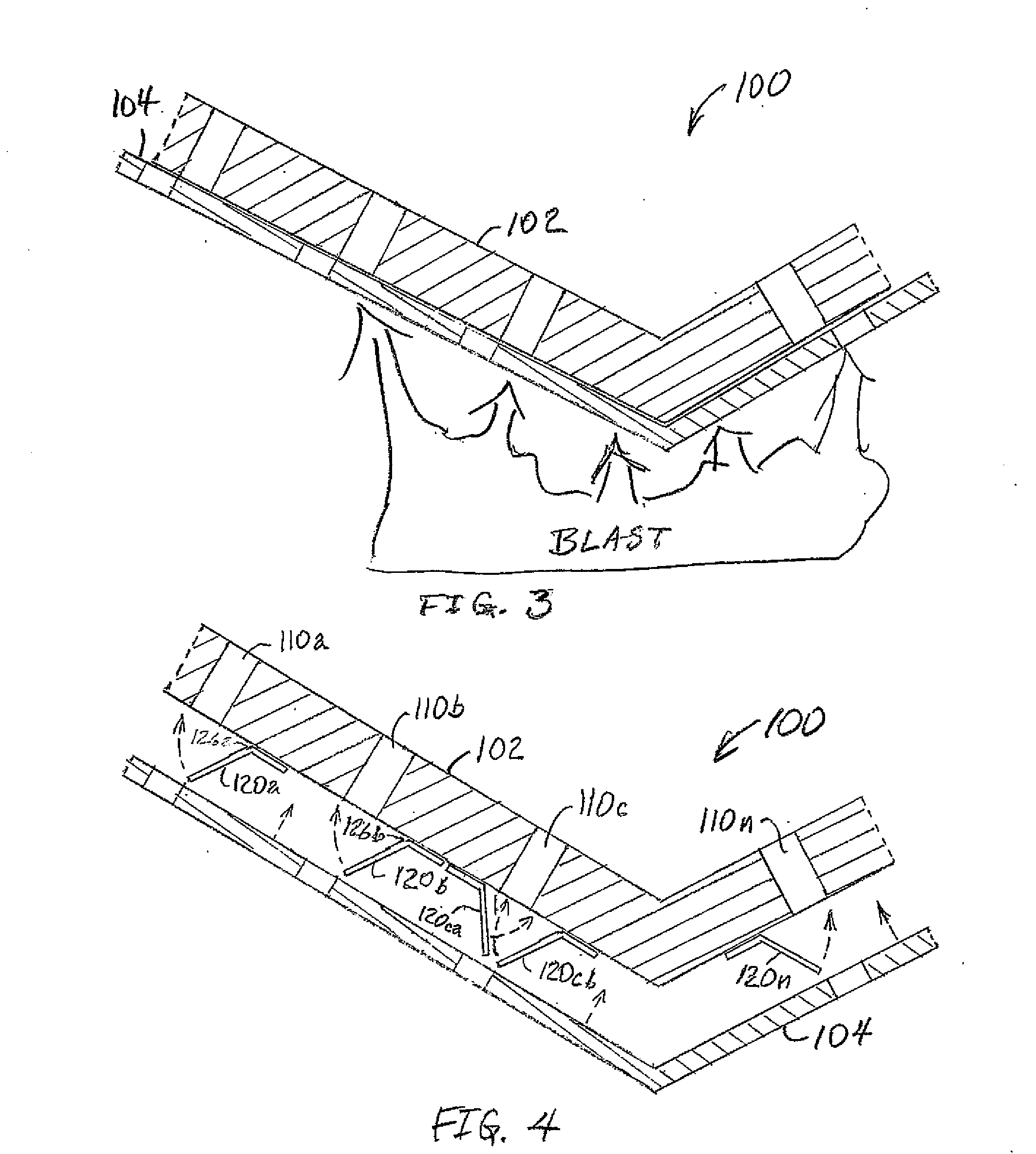
[0010]Between the inner and outer layer a valve subsystem may be implemented. The valve subsystem is generally rapidly closed by the pressure generated by an explosion. In simple form, the valve subsystem can be flaps of material which are forced over the holes in the inner structure by the movement of the outer structure. The valve subsystem closing action will generally reduce or prevent most of the high pressure gasses generated by the under-vehicle explosion from bypassing the inner “V” and thus provide significant blast protection; well beyond the protection that the perforated structure would provide without rapidly closing valve subsystem.

Problems solved by technology

Buildup of such debris materials would generally add weight to the vehicle, and could result in preventing the valves from functioning properly.

Method used


Image

  • Vented Armor V Structure
  • Vented Armor V Structure
  • Vented Armor V Structure

Examples


Embodiment Construction

)

[0052]Definitions and Terminology:

[0053]The following definitions and terminology are applied as understood by one skilled in the appropriate art.

[0054]The singular forms such as “a,”“an,” and “the” include plural references unless the context clearly indicates otherwise. For example, reference to “a material” includes reference to one or more of such materials, and “an element” includes reference to one or more of such elements.

[0055]As used herein, “substantial” and “about”, when used in reference to a quantity or amount of a material, dimension, characteristic, parameter, and the like, refer to an amount that is sufficient to provide an effect that the material or characteristic was intended to provide as understood by one skilled in the art. The amount of variation generally depends on the specific implementation. Similarly, “substantially free of or the like refers to the lack of an identified composition, characteristic, or property. Particularly, assemblies that are identifi...


PUM


Abstract

An armor structure for a vehicle underbody. The armor structure includes an inner plate that is mounted proximate to the vehicle underbody, the inner plate having a plurality of first openings; and an outer plate that is mounted distal to the vehicle underbody, the outer plate having a plurality of second openings. The inner plate and the outer plate are substantially parallel and separated by a spacing. The inner plate and the outer plate each have substantially equal V bends at an obtuse angle, and the V bends in the inner plate and the outer plate are aligned. The first openings and the second openings are (i) aligned across the spacing from each other, and (ii) substantially equal in area. When an underbody blast event is encountered by the vehicle, the outer plate is forced towards, and substantially against the inner plate such that there is no longer fluid communication through the first openings.

Description

GOVERNMENT INTEREST[0001]The invention described here may be made, used and licensed by and for the U.S. Government for governmental purposes without paying royalty to me.BACKGROUND OF THE INVENTION[0002]1. Field of the Invention[0003]The present invention generally relates to a vented armor V structure.[0004]2. Background Art[0005]Recently, a class of military vehicles known as Mine Resistant Ambush Protected (MRAP) vehicles has become popular due to the protection which is provided against mines, improvised explosive devices (IEDs), and the like. The most salient feature of the MRAP is the “V” shaped lower hull armor which has proven effective at deflecting the blast of under-vehicle explosions. There have been numerous efforts to retrofit “V” shaped blast shields on vehicles which were not designed to accept such protection. In some cases the added protection is well tolerated by the host vehicle, in other cases automotive problems occurred. The primary source of automotive probl...

Claims


Application Information

Patent Timeline
IPC IPC(8): F41H7/02F41H5/04
CPCF41H7/042
Inventor GONZALEZ, RENE' G.
Owner UNITED STATES OF AMERICA THE AS REPRESENTED BY THE SEC OF THE ARMY
Learn More