
Self-locking type shutter device

a self-locking, gate device technology, applied in the direction of instruments, wing accessories, door/window fittings, etc., can solve problems such as complex structure, reduce the destructive degree of glue on the gate device, prevent the gate device from being damaged, and reduce the contact area

Inactive Publication Date: 2012-08-02
GRG BAKING EQUIP CO LTD
View PDF14 Cites 14 Cited by
  • Summary
  • Abstract
  • Description
  • Claims
  • Application Information

AI Technical Summary

Benefits of technology

The present invention provides a self-locking gate structure for a financial self-service instrument that prevents unauthorized opening. The gate device includes an integral welded frame, a door, and a power transmission mechanism. The power transmission mechanism includes an electric motor and one-way folded connecting rod mechanisms. The connecting rods are hinged together through a shaft and the other end is connected to the door through another shaft. The edges of the door are provided with POM plastic sphere convex dots to guide liquid glue and prevent damage to the gate device. The technical effects of the invention include preventing foreign matters and liquid glue from sticking and minimizing damage to the gate device.

Problems solved by technology

However, it also provides an opportunity for criminals to steal or intercept money from depositors.
However, in this manner, it is inevitable to form a gap between the gate and a base plate when assembling the gate, and thus criminals may move the gate stopper from the gap with a thin rigid sheet, so that the gate may be easily opened.
Obviously, it is an important problem of designing the financial self-service instrument to improve the safety and reliability of the cash outlet gate and prevent the cash outlet gate from being illegally opened.
The conventional gate locking device generally has many members, and thus has a complex structure.

Method used


Image

  • Self-locking type shutter device
  • Self-locking type shutter device
  • Self-locking type shutter device

Examples


Embodiment Construction

[0027]Hereinafter, the technical solutions in embodiments of the present invention will be described clearly and completely with reference to drawings of the embodiments of the present invention. It is apparent that the embodiments to be described are merely a portion of embodiments of the present invention, but not all of the embodiments. Based on the embodiments of the present invention, all of other embodiments made by those skilled in the art without inventive effort fall into the protection scope of the present invention.

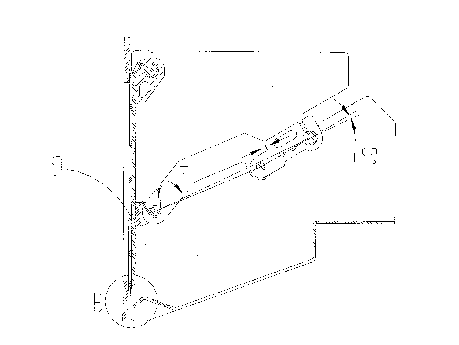
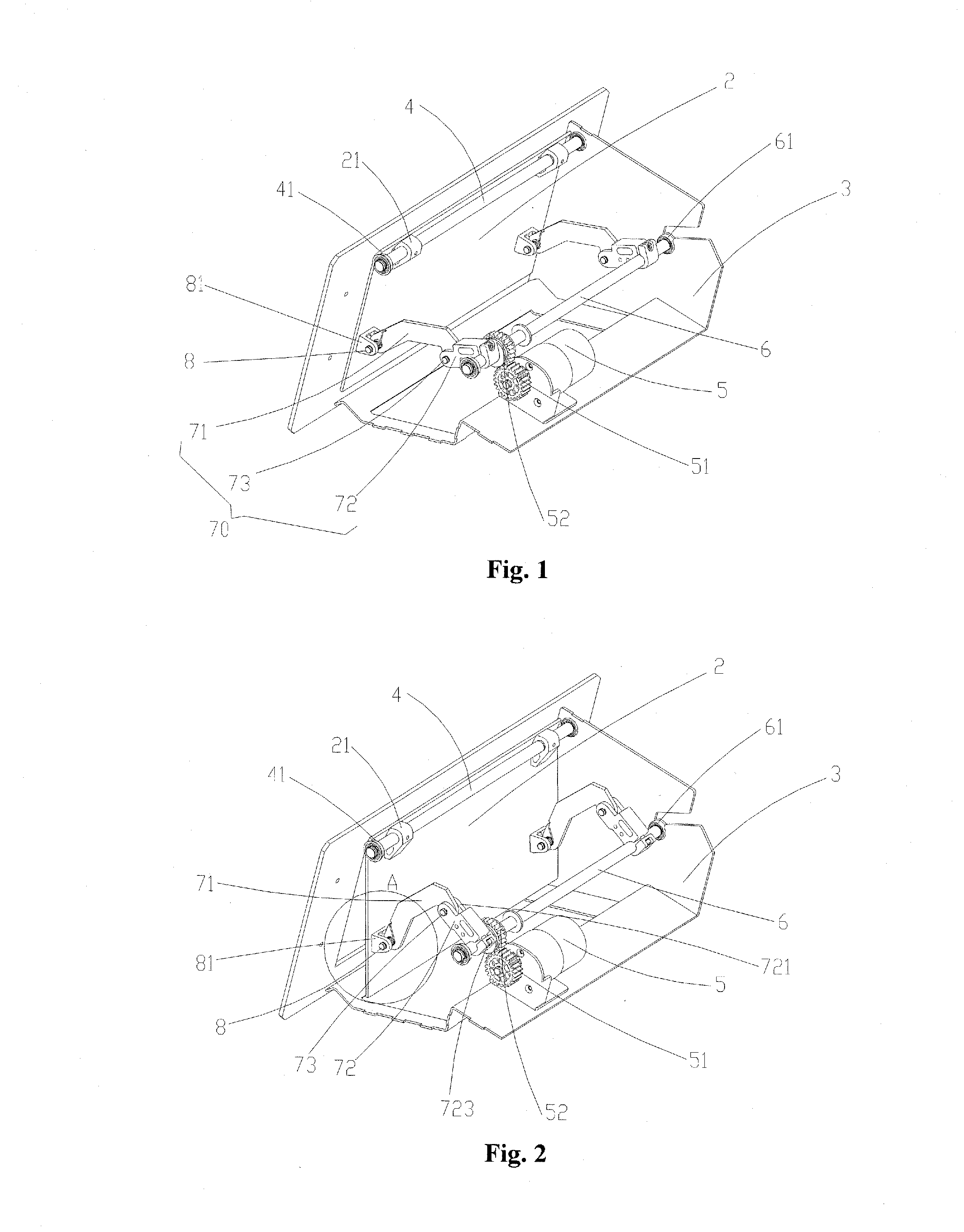
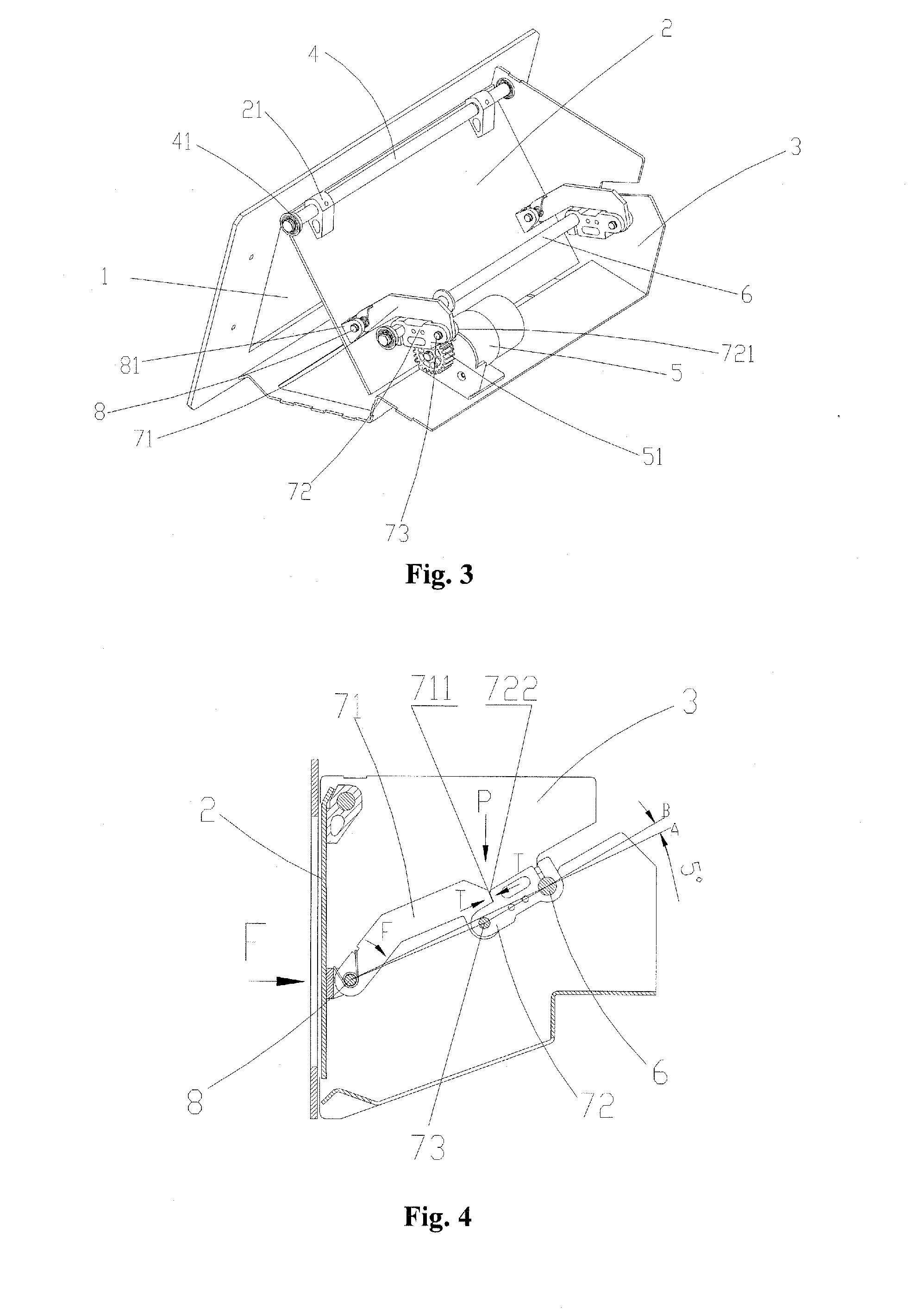
[0028]Referring to FIGS. 1 to 3, the preferred gate device of the cash inlet / outlet 1 applied in the financial self-service instrument according to the present invention includes an integral welded frame 3, a door 2 and a power transmission mechanism. The door 2 is of a plate shape. One side of the door 2 is installed to the frame 3 through a first rotation shaft 4 and is rotatable around the first rotation shaft 4. Specifically, a pair of shaft seats 21 is fix...


PUM


Abstract

A self-locking type shutter device is provided. The device is arranged in a financial self-service equipment, so as to open or close a cash depositing / withdrawing port (1) of the financial self-help service equipment. The device comprises a frame (3) integrally welded, a gate (2) and a power transmission mechanism. The gate (2) is arranged on the frame (3) by a first rotation shaft (4) and can rotate around the first rotation shaft (4). The power transmission mechanism is fixed on the frame (3), so as to provide the gate (2) with rotation power. The power transmission mechanism comprises a motor (5) and at least one unidirectional folding linkage mechanism (70). The device can be self-locked via the unidirectionally folding linkage mechanism (70).

Description

[0001]The present application claims the benefit of priority to Chinese patent application No. 200910193709.7 titled “SELF-LOCKING TYPE SHUTTER DEVICE”, filed with the Chinese State Intellectual Property Office on Nov. 6, 2009. The entire disclosures thereof are incorporated herein by reference.FIELD OF THE INVENTION[0002]The present invention relates to a cash inlet / outlet gate device for financial self-service instruments, and more particularly, to a self-locking gate device.BACKGROUND OF THE INVENTION[0003]At present, the financial self-service instruments are widely used. Independent self-service instruments may provide 24-hour uninterrupted service, so as to provide many advantages to people's lives. Unattended automatic teller machines are convenient to depositors. However, it also provides an opportunity for criminals to steal or intercept money from depositors. As the automatic teller machine is widely installed, criminal cases for the automatic teller machine are also incre...

Claims


Application Information

Patent Timeline
Patent Type & Authority Applications(United States)
IPC IPC(8): E06B5/11E05F11/54
CPCG07D11/0018Y10S902/17Y10S902/08G07D11/14
Inventor GUAN, ZEYANCHEN, XIAODIANWEI, DONGWANG, NIAN
Owner GRG BAKING EQUIP CO LTD
Learn More