Air guide plate for automobile and sealing structure

a technology for sealing structure and air guide plate, which is applied in the direction of engine sealing, propulsion parts, vehicle components, etc., can solve the problems of reducing leaking or escaping air guided by the air guide surface of the air guide plate, and affecting the cooling efficiency of the radiator, so as to achieve smooth airflow and reduce the cost , the effect of easy realization of stable sealing properties

a technology for sealing structure and air guide plate, which is applied in the direction of engine sealing, propulsion parts, vehicle components, etc., can solve the problems of reducing leaking or escaping air guided by the air guide surface of the air guide plate, and affecting the cooling efficiency of the radiator, so as to achieve smooth airflow and reduce the cost , the effect of easy realization of stable sealing properties

US20120193156A1Inactive Publication Date: 2012-08-02KOJIMA PRESS IND CO LTD

Image

  • Air guide plate for automobile and sealing structure
  • Air guide plate for automobile and sealing structure
  • Air guide plate for automobile and sealing structure

Examples


first embodiment

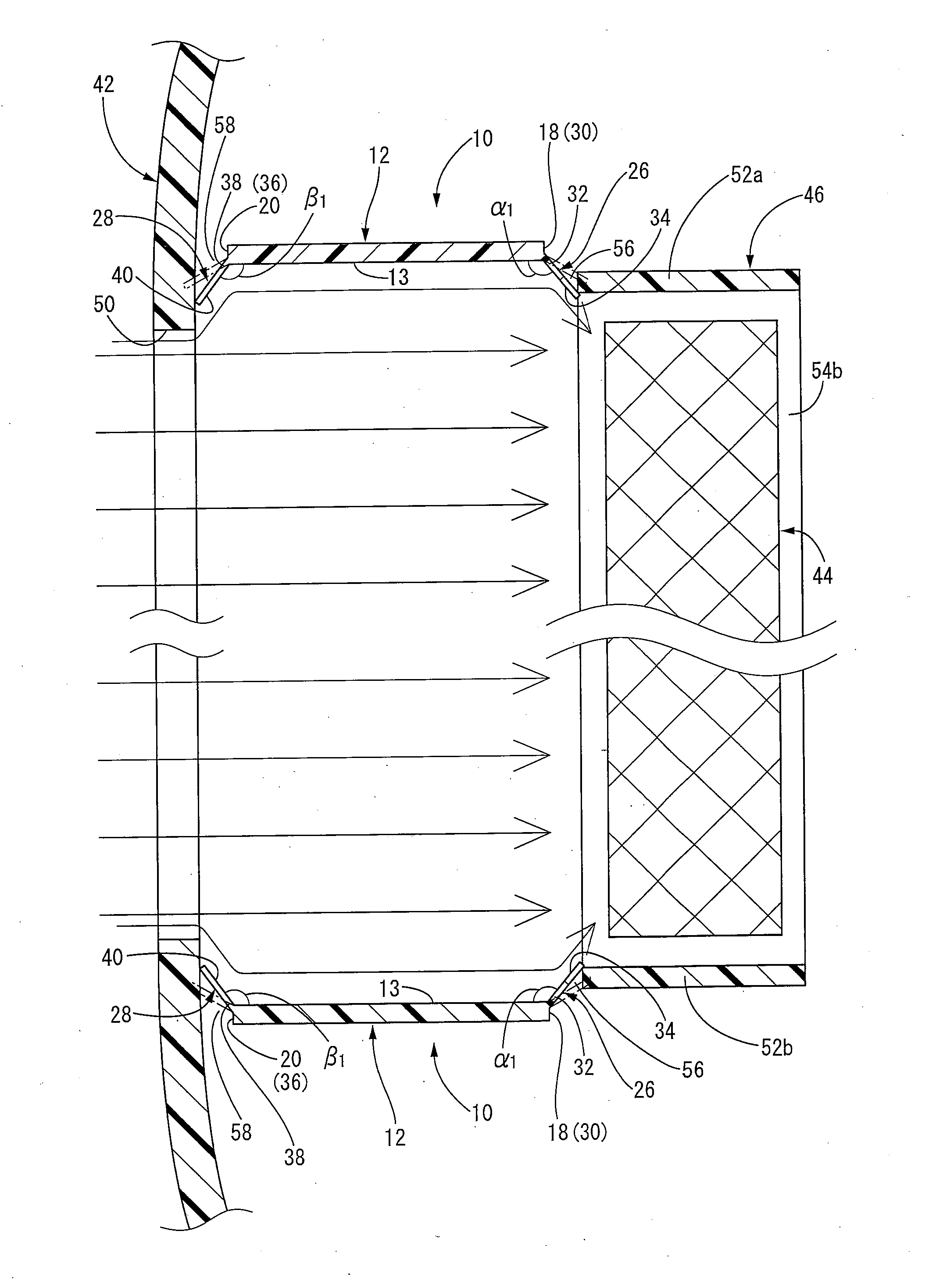
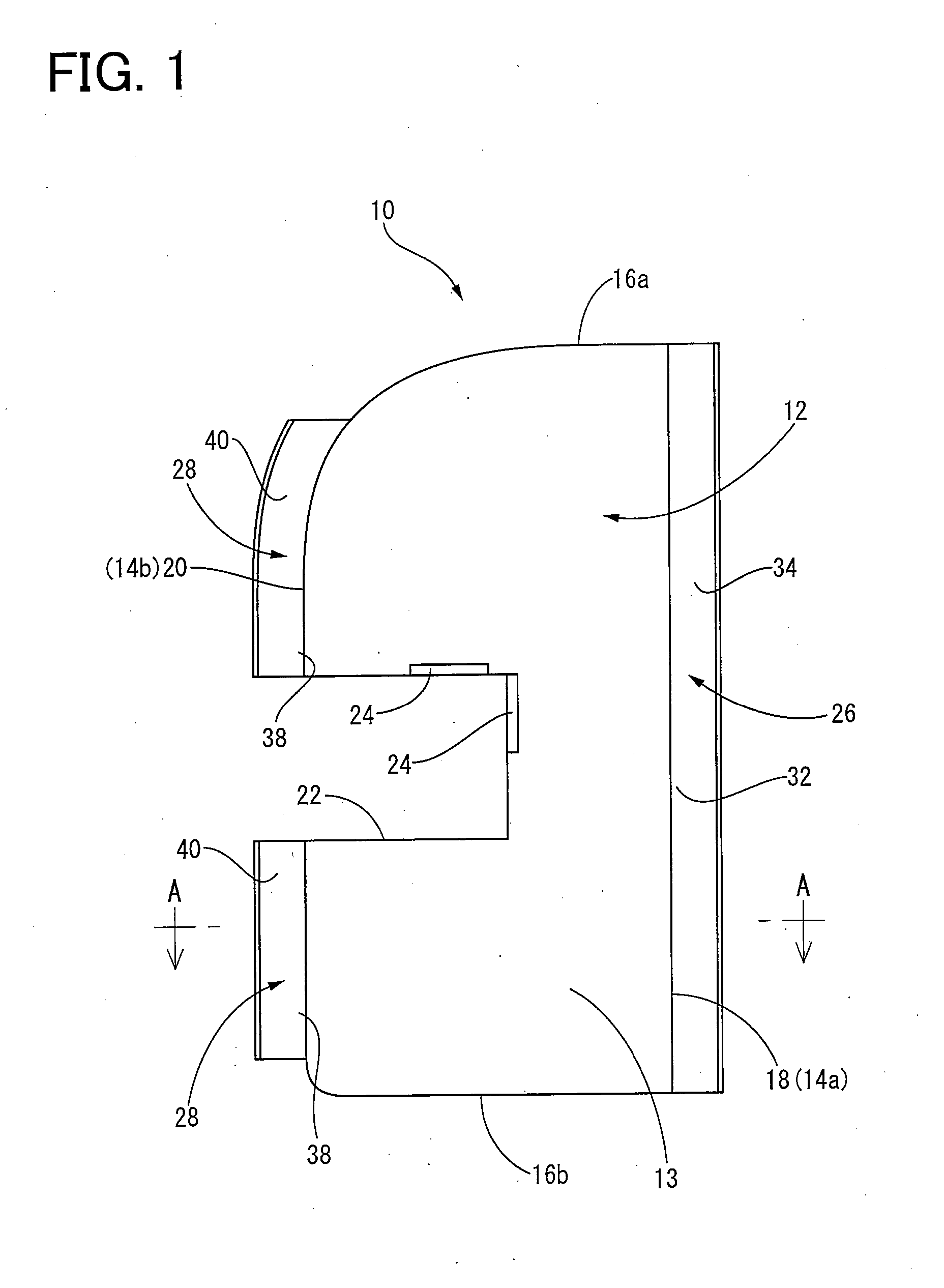
[0047]Initially, FIG. 1 shows a front view of an air guide plate in accordance with the present invention, which is disposed between a bumper cover and a shroud of an automobile, and FIG. 2 shows a cross sectional view of the air guide plate. As apparent from FIG. 1 and FIG. 2, an air guide plate 10 of the present embodiment includes a plate body 12 made of resin. Hereinafter, the up and down direction in FIG. 1 is referred to as the vertical direction of the air guide plate 10, and the horizontal direction in FIG. 1 is referred to as the front and back direction of the air guide plate 10, based on the state where the air guide plate 10 is installed in an automobile (see FIG. 3 and FIG. 4).

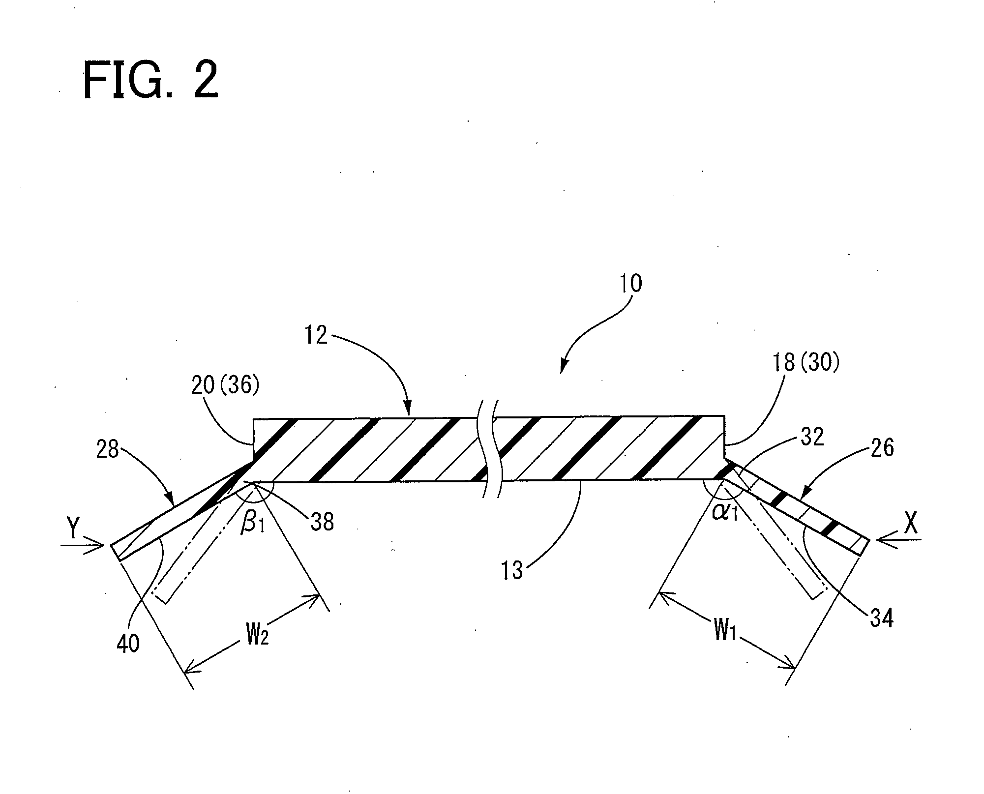
[0048]More specifically described, the plate body 12 has a flat plate shape which is a long rectangular shape as a whole. One surface of the plate body 12 is made as a flat air guide surface 13. The air guide surface 13 guides the airflow introduced into the automobile from the bumper cover side t...

second embodiment

[0099]In the air guide plate 60 of the second embodiment, the front sealing member 28 extends frontward from the front edge surface 36 such that the angle β1 between the base end portion 38 of the front sealing member 28 and the air guide surface 13 is within a range of more than 180 degrees to less than 270 degrees. Thus, as shown in FIG. 6, when the base end portion 38 of the front sealing member 28 is subjected to flexural deformation such that the tip end portion of the front sealing member 28 is in contact with the inner surface of the bumper cover 42, the air guide surface 13 and a periphery of the opening of the air inlet 50 can be positioned in a straight line in the front and back direction of the vehicle. Thus, the air passed through the air inlet 50 can be guided to the radiator 44 side more efficiently.

[0100]To confirm that the air guide plate having the structure of the present invention has the above-described excellent characteristic, the inventors of the present inve...


PUM


Abstract

An air guide plate is provided which can easily realize stable sealing properties with respect to an automobile part disposed near the air guide plate and which can provide a structure in which the air guide plate and the automobile part are not collided, at a low cost. The air guide plate 10 includes a plate body 12 made of resin and rear and front sealing members 26, 28 integrally formed on rear and front end sections 18, 20 of the plate body 12. The sealing members 26, 28 are flexible at at least base end portions 32, 38 thereof and extend from the end sections 18, 20 of the plate body 12 at an angle of more than 90 degrees to less than 180 degrees with respect to the air guide surface 13 of the plate body 12.

Description

[0001]The present application is based on Japanese Patent Application No. 2011-019901 filed on Feb. 1, 2011, the contents of which are incorporated herein by reference.BACKGROUND OF THE INVENTION[0002]1. Field of the Invention[0003]The present invention relates to an air guide plate for an automobile and a sealing structure, and in particular to an improved structure of an air guide plate which is arranged at the front of an automobile and guides an airflow produced during driving of the automobile to a radiator, and an air guide plate having such an improved structure, and further a novel structure for sealing a gap formed between the air guide plate and an automobile part positioned near the air guide plate.[0004]2. Discussion of Related Art[0005]Generally, in an automobile, when separate automobile parts are assembled together, a predetermined gap or space, i.e., a designed gap, is provided between the automobile parts positioned close to each other, for prevention of noise, dama...

Claims


Application Information

Patent Timeline
02 Aug 2012
Publication
US20120193156A1
IPC
B60K11/08; F16J15/02
CPC
B60K11/08
Inventors
HIRANO, KATSUHISA