

Temperature correcting current-controlled ring oscillators
- Summary
- Abstract
- Description
- Claims
- Application Information
AI Technical Summary
Benefits of technology
Problems solved by technology
Method used
Image

Examples
Embodiment Construction
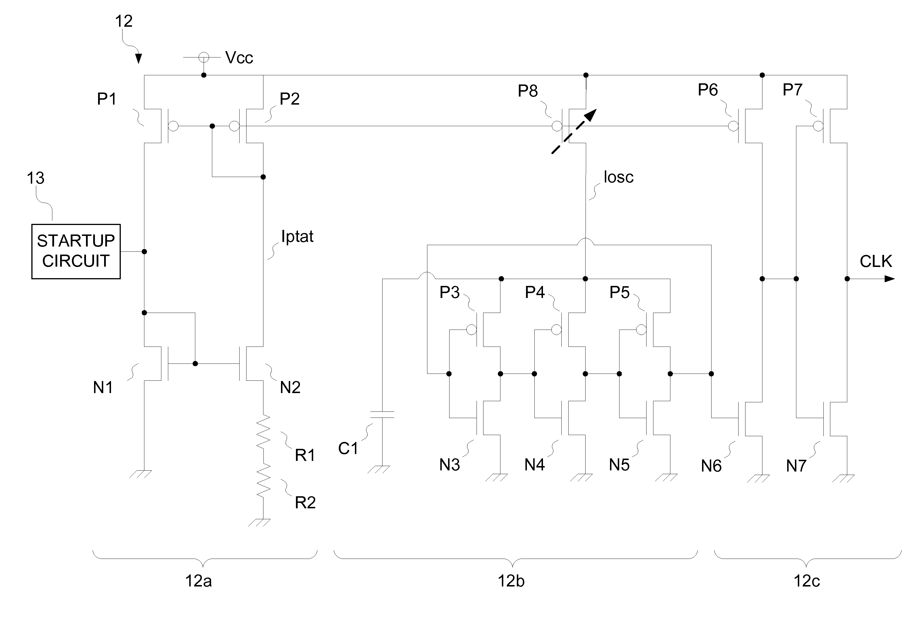
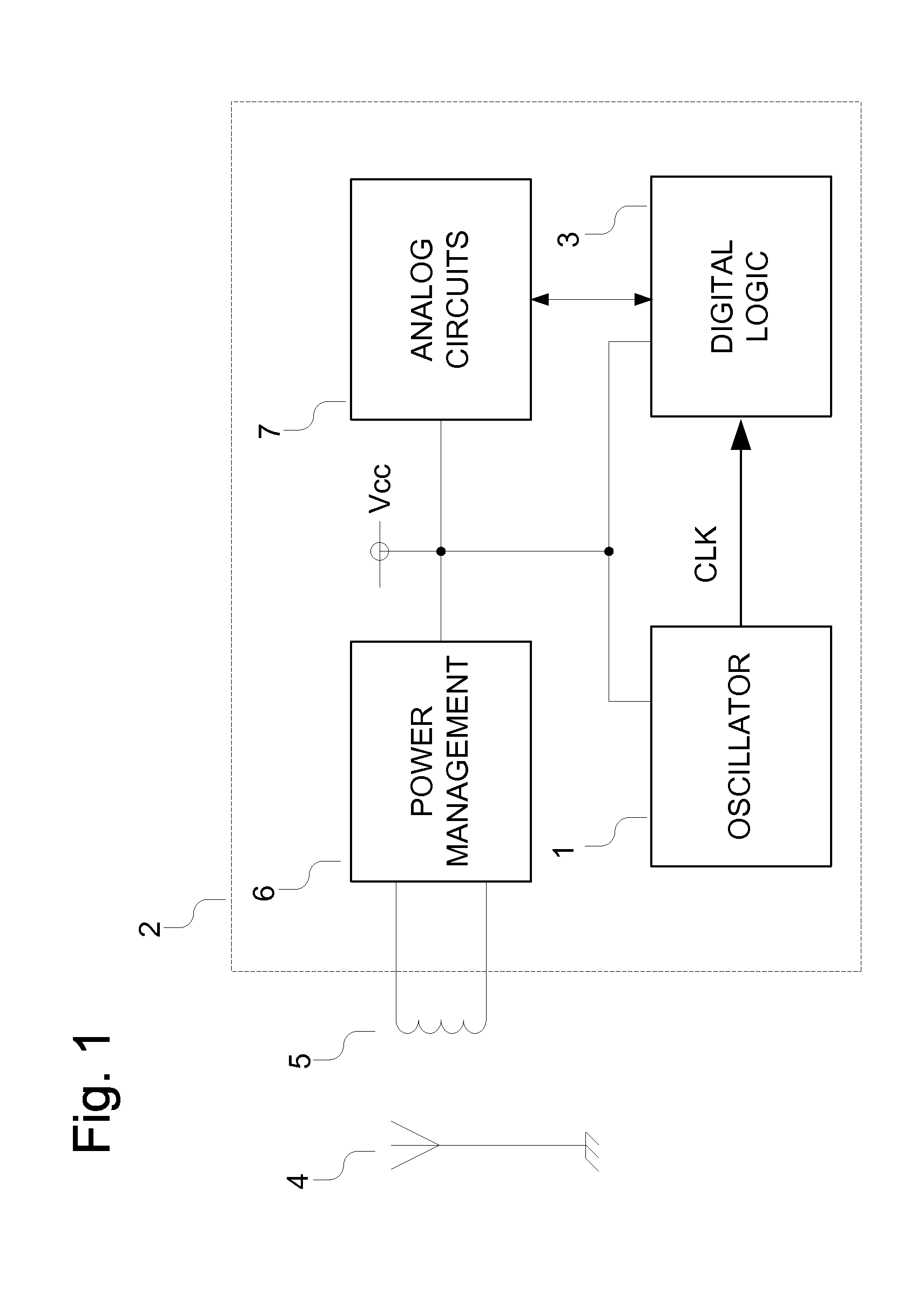
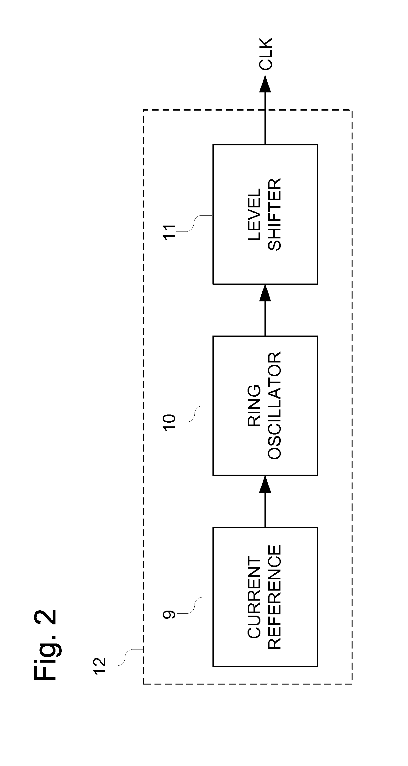
[0022]FIG. 1 depicts an exemplary RFID device 2. Device 2 is powered in a known manner by an antenna 5, which, during device operation, is located within the RF field emitted by transmitter 4 (“within” is used generally and means that the RF field is sufficiently strong to result in power generation in the RFID device 2). The amount of power required by the device 2 for operation directly affects the maximum distance from the transmitter 4 that the device 2 can operate at. The oscillator 1 in the device 2 supplies the clock signals(s) used by the digital logic 3 in the device 2.
[0023]A simple very low power oscillator could be made by using a current starved ring oscillator and trimming the bias current required so that the oscillator operates at a specific frequency. However the operating frequency of that ring oscillator will be temperature dependent when the ring oscillator is biased with a fixed reference current.
[0024]A proportional to absolute temperature (PTAT) current source...
PUM
 Abstract
Description
Claims
Application Information