Antenna apparatus, radar apparatus and on-vehicle radar system

a radar and vehicle technology, applied in the field of antenna apparatus, can solve the problems of inability to cover a broader detection area, inability to immediately judge whether a detected target is a stopped object (e.g., roadside object) or a moving object (e.g., vehicle), and the relative speed of the target to the radar apparatus is zero, so as to improve the reliability of the movement judgment uni

Inactive Publication Date: 2012-08-02
DENSO CORP
View PDF6 Cites 72 Cited by
  • Summary
  • Abstract
  • Description
  • Claims
  • Application Information

AI Technical Summary

Benefits of technology

[0021]In this case, radiation of electromagnetic waves leaking from the electric supply line can be reduced. Accordingly, disturbance in the directivity of the second antenna section is suppressed, which disturbance would otherwise have been caused by the leakage of radiation from the electric supply line.
[0049]It is usually considered that, if the side detection target is a stopped object, a moving object, which is moving on the same traffic lane as the side detection target, needs to travel while passing the side detection target. Due to this, there is a low possibility that a target, which is moving on the adjacent traffic lane at the rear of own vehicle, is detected. In other words, if a moving target exists at the rear of the adjacent traffic lane, there is a high possibility that the target detected is a moving target. Thus, the above judgment of the movement judgment unit becomes effective.

Problems solved by technology

Thus, the above related art has suffered from a problem of not being able to cover a broader detection area.
Therefore, it is impossible to immediately judge whether a detected target is a stopped object (e.g., roadside object) or a moving object (e.g., vehicle) needed to be tracked.
In particular, when CW is used without being frequency-modulated, a target whose relative speed to own radar apparatus is zero cannot be detected.

Method used


Image

  • Antenna apparatus, radar apparatus and on-vehicle radar system
  • Antenna apparatus, radar apparatus and on-vehicle radar system
  • Antenna apparatus, radar apparatus and on-vehicle radar system

Examples


first embodiment

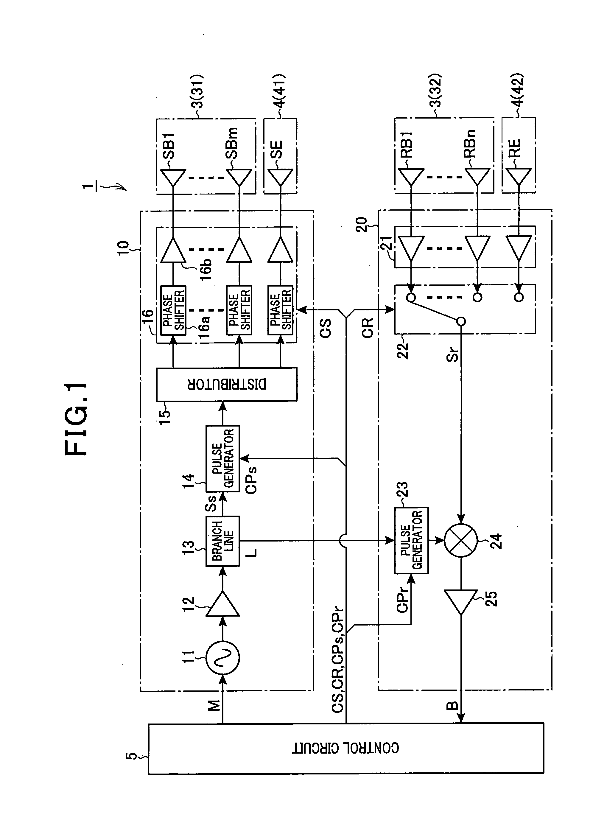
[0077]FIG. 1 is a block diagram illustrating a general configuration of a radar apparatus 1 according to a first embodiment of the present invention.

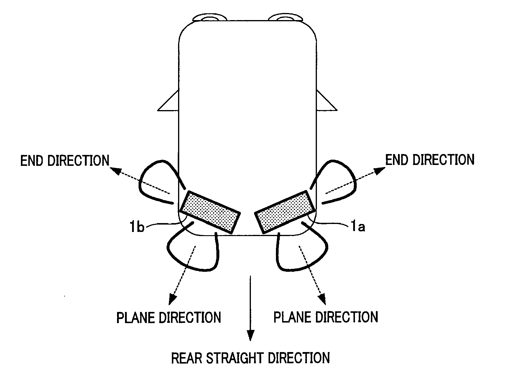
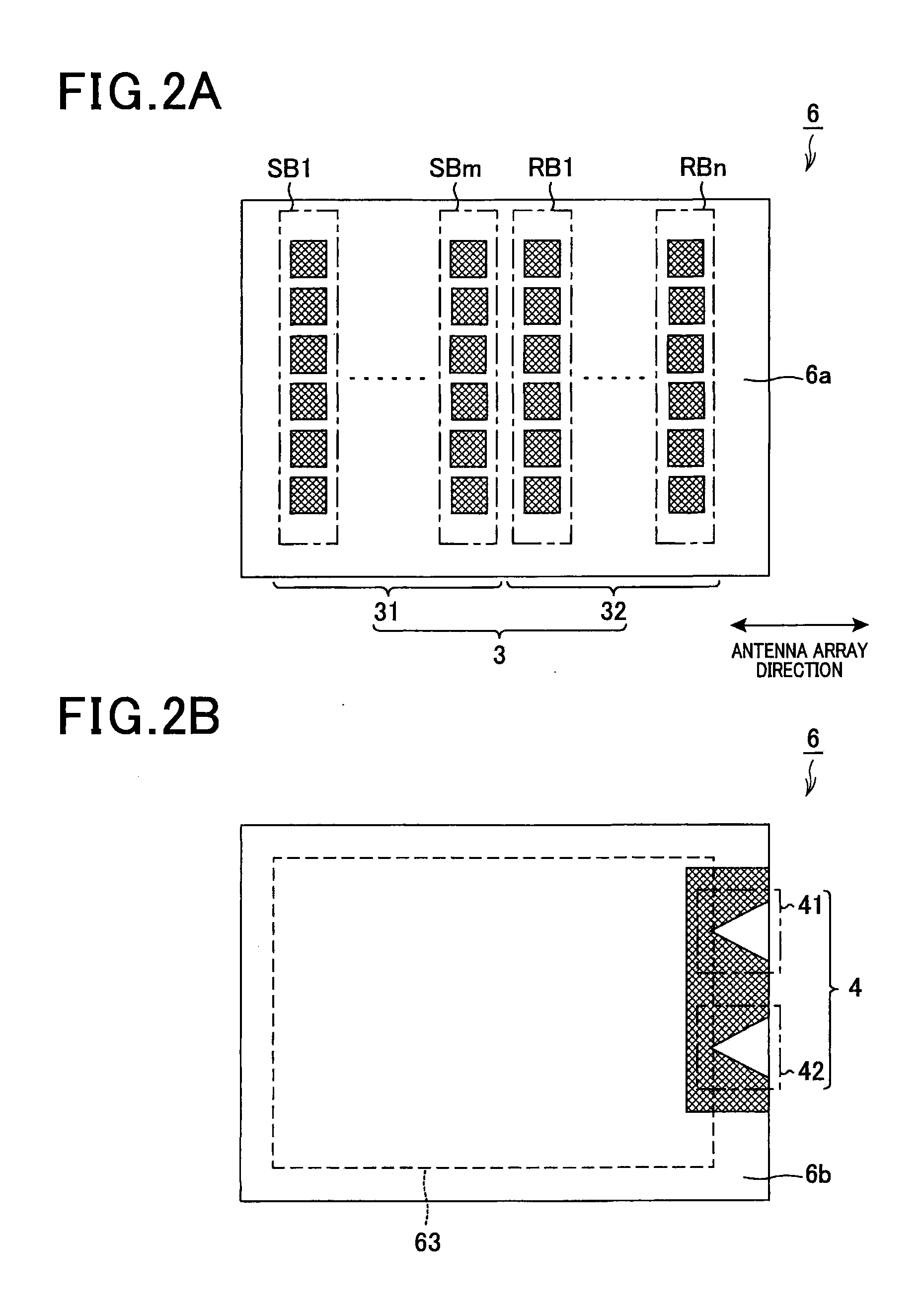
[0078]As shown in FIG. 1, the radar apparatus 1 includes a first antenna section 3 (first antenna) and a second antenna section 4 (second antenna). The first antenna section 3 includes a first transmitting antenna group 31 and a first receiving antenna group 32. The first transmitting antenna group 31 is composed of an m (m is an integer of 2 or more) number of first antenna elements SBi (i=1 to m). The first receiving antenna group 32 is composed of an n (n is an integer of 2 or more) number of first antenna elements RBj (j=1 to n). The second antenna section 4 includes a second transmitting antenna 41 composed of a single second antenna element SE and a second receiving antenna 42 composed of a single second antenna element RE. The second antenna section 4 is configured so that the main radiation direction is different from that of th...

second embodiment

[0156]With reference to FIG. 13, hereinafter is described a second embodiment of the present invention. In the second embodiment as well as in the modifications described later, the components identical with or similar to those in the first embodiment are given the same reference numerals for the sake of omitting unnecessary explanation.

[0157]The second embodiment is different from the first embodiment in the system control process performed by the radar apparatus 1a that is the master unit. Therefore, the second embodiment is described focusing on the difference.

[0158]FIG. 13 is a flow diagram illustrating a system control process according to the second embodiment.

[0159]When the system control process is started, it is determined, at step S510, first, whether or not the vehicle is in a state of moving forward. Whether the vehicle is in a state of moving forward is determined in a manner similar to step S310.

[0160]If the vehicle is in a state of moving forward, control proceeds to ...

third embodiment

[0178]FIG. 16 is a block diagram illustrating a general configuration of a radar apparatus 101 according to a third embodiment of the present invention.

[0179]As shown in FIG. 16, the radar apparatus 101 includes a first antenna section 103 (first antenna) and a second antenna section 104 (second antenna). The first antenna section 103 includes a first transmitting antenna group 1031 and a first receiving antenna group 1032. The first transmitting antenna group 1031 is composed of an m (m is an integer of 2 or more) number of first antenna elements SBi (i=1 to m). The first receiving antenna group 32 is composed of an n (n is an integer of 2 or more) number of first antenna elements RBj (j=1 to n). The second antenna section 104 includes a second transmitting antenna 1041 made up of a single second antenna element SE and a second receiving antenna 1042 made up of a single second antenna element RE. The second antenna section 104 is configured so that the main radiation direction is d...


PUM


Abstract

An antenna apparatus includes a substrate, a first antenna, and a second antenna. The substrate includes two or more pattern-forming layers which are layered via at least one insulating layer. The two or more pattern-forming layers include a first pattern-forming layer and a second pattern-forming layer which are different from each other. The first pattern-forming layer forms one of both outer layers located at both surfaces of the substrate. The first antenna is formed on the first pattern-forming layer, includes a plurality of antenna elements arrayed in a row, and radiates electromagnetic waves in a layer direction of the plurality of layers. The second antenna is formed on the second pattern-forming layer, is arranged on at least one side of both sides of the antenna array direction of the plurality of antenna elements of the first antenna section, and radiates electromagnetic waves in the antenna array direction.

Description

CROSS-REFERENCE TO RELATED APPLICATION[0001]This application is based on and claims the benefit of priorities from earlier Japanese Patent Application Nos. 2011-018102 and 2011-018101 both filed Jan. 31, 2011, the descriptions of which are incorporated herein by reference.BACKGROUND OF THE INVENTION[0002]1. Technical Field of the Invention[0003]The present invention relates to an antenna apparatus, a radar apparatus, and an on-vehicle radar system, and in particular to an antenna apparatus used for transmitting / receiving electromagnetic waves, a radar apparatus including the antenna apparatus, an on-vehicle radar apparatus mounted on a vehicle which detects targets (objects) around a vehicle, and an on-vehicle radar system including the radar apparatus.[0004]2. Related Art[0005]In the radar apparatus of the related art, some techniques for realizing a broad detection area are known. As one of such techniques, JP-A-2007-049691 discloses an antenna module including a first antenna and...

Claims


Application Information

Patent Timeline
Patent Type & Authority Applications(United States)
IPC IPC(8): G01S13/93G01S13/00H01Q3/00G01S13/931
CPCG01S13/931H01Q9/285H01Q13/085H01Q21/062G01S2013/9385G01S2013/9317G01S2013/9332G01S2013/9378H01Q21/064G01S13/0209G01S13/10G01S13/32G01S13/345G01S13/347G01S13/582G01S13/584G01S13/87G01S2013/9315G01S2013/93274G01S2013/93272G01S7/28G01S7/35G01S13/04G01S13/58
Inventor YUKUMATSU, MASANOBUKONDOU, ASAHIMIYAKE, YASUYUKI
Owner DENSO CORP
Why Eureka
Try Eureka