Multi-stage beam contacts

a beam contact and multi-stage technology, applied in the direction of coupling device connection, engagement/disengagement of coupling parts, electric discharge lamps, etc., can solve the problems of affecting signal capability, generating reflection, cross-talk, electromagnetic radiation, etc., and achieving low initial insertion force

Active Publication Date: 2012-08-02
AMPHENOL CORP
View PDF3 Cites 123 Cited by
  • Summary
  • Abstract
  • Description
  • Claims
  • Application Information

AI Technical Summary

Benefits of technology

[0011]Accordingly, it is an object of the invention to provide daughtercard mating contacts that form reliable connections with backplane mating contacts. It is another object of the invention to provide mating contacts which have a low initial insertion force and a normal working force when fully mated. It is yet another object of the invention to provide a contact assembly with contacts bearing on a divider, separating the mating contacts having equal and opposite forces provides a self-centering effect when the connector halves are mated.

Problems solved by technology

Electronic systems have generally become smaller, faster, and functionally more complex.
As signal frequencies increase, there is a greater possibility of electrical noise, such as reflections, cross-talk, and electromagnetic radiation, being generated in the connector.
At 20-30 GHz, the traditional 2.0 mm to 3.0 mm contact over-travel in present contact systems creates an antenna / stub that resonates, negatively impacting the signal capability.

Method used


Image

  • Multi-stage beam contacts
  • Multi-stage beam contacts
  • Multi-stage beam contacts

Examples


Embodiment Construction

[0036]In describing a preferred embodiment of the invention illustrated in the drawings, specific terminology will be resorted to for the sake of clarity. However, the invention is not intended to be limited to the specific terms so selected, and it is to be understood that each specific term includes all technical equivalents that operate in a similar manner to accomplish a similar purpose.

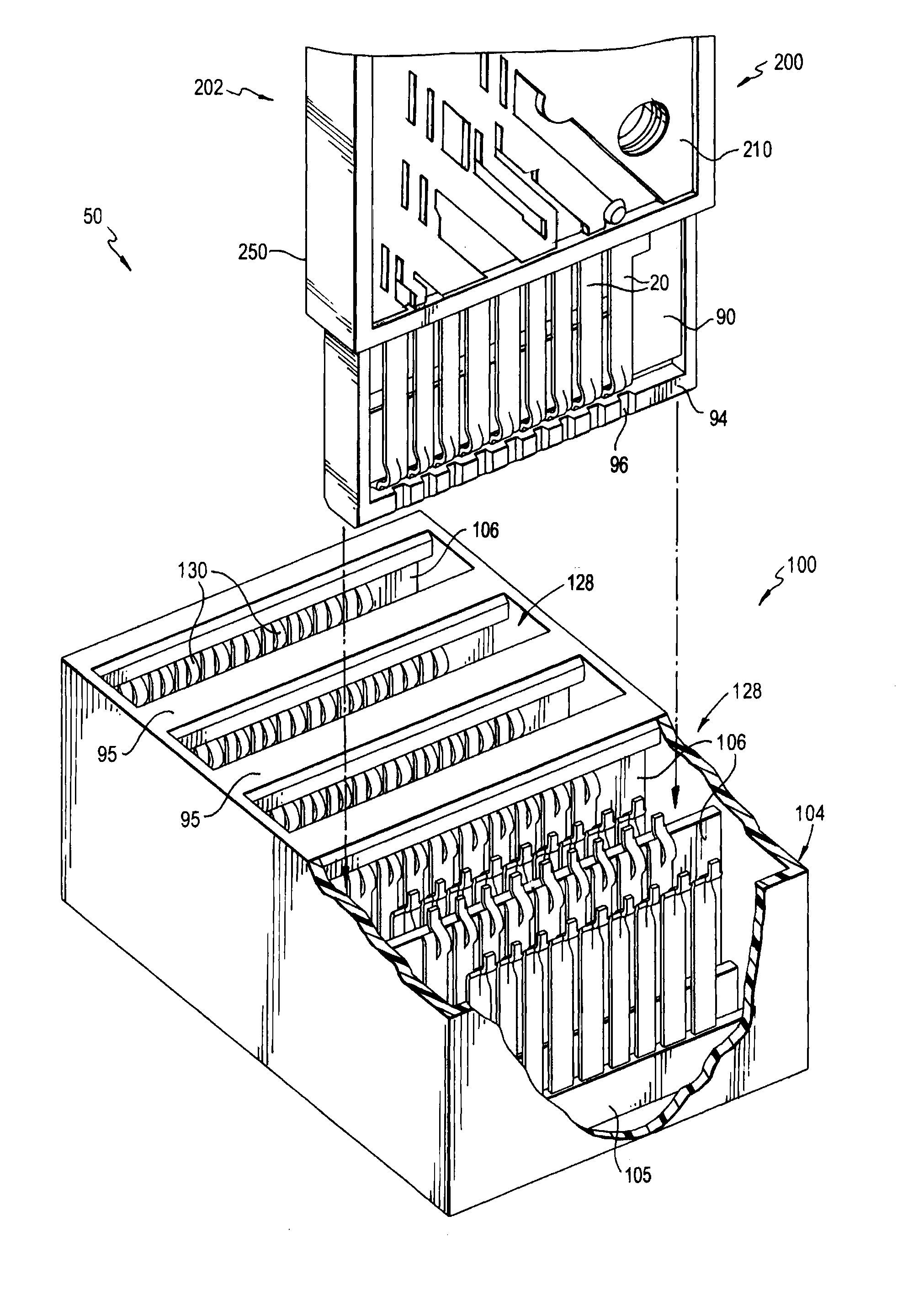
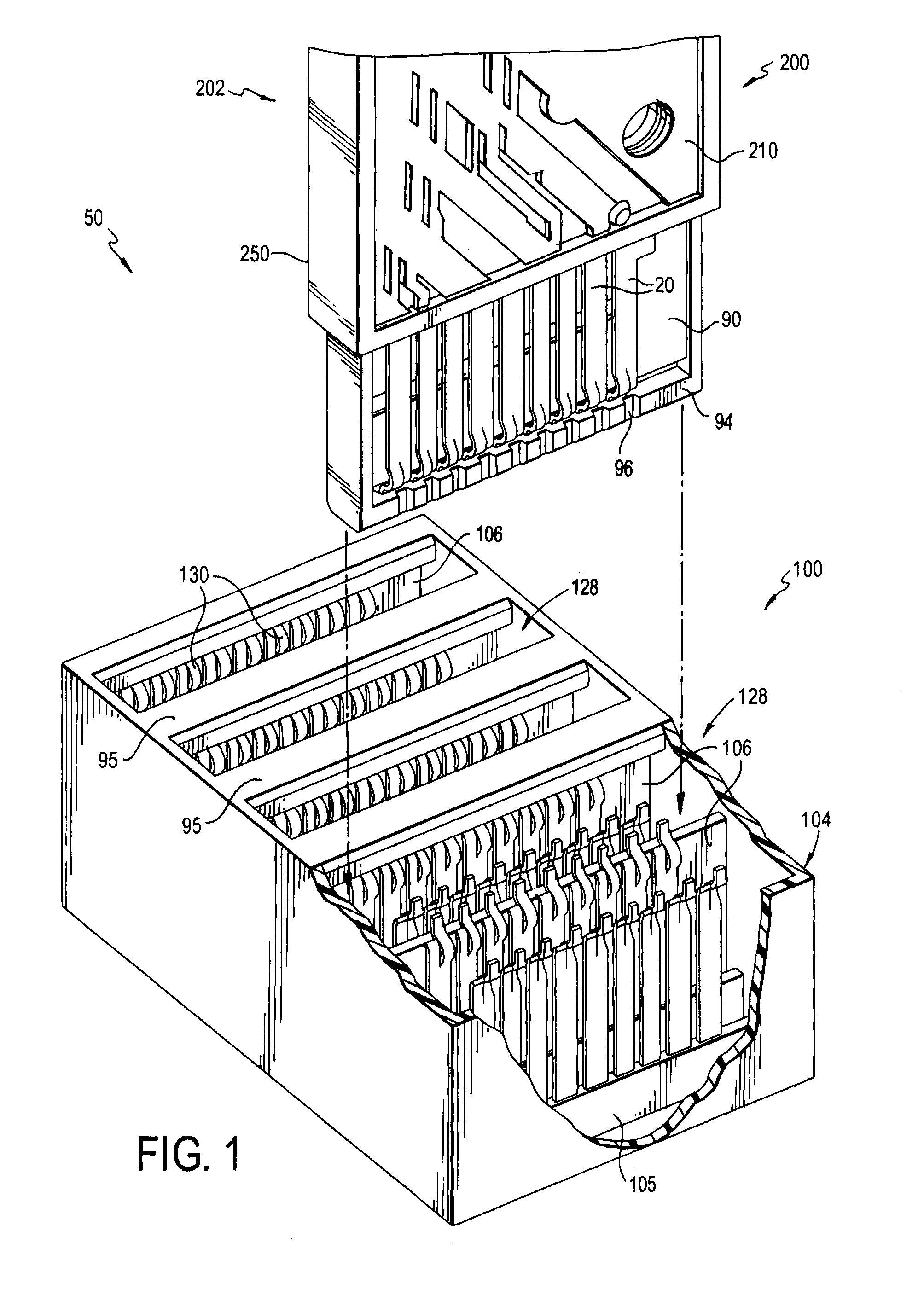
[0037]Turning to the drawings, FIG. 1 shows an electrical interconnection system 50 which includes a backplane connector 100 and daughtercard connector 200. The backplane connector 100 connects to a backplane or PCB (not shown). The daughtercard connector 200 has a wafer pair 202 which mates with the backplane connector 100 and connects to a daughtercard (not shown). The daughtercard connector 200 creates electrical paths between a backplane and a daughtercard. Though not expressly shown, the interconnection system 50 may interconnect multiple daughtercards having similar daughtercard connectors ...


PUM


Abstract

An electrical connector has a first wafer having a first housing with a first plurality of contact beams extending from the first housing in a first plane. A second wafer has a second housing with a second plurality of contact beams extending from said second housing in a second plane substantially parallel to the first plane. A dividing panel member extends from the insulative housing between the first plurality of contact beams and the second plurality of contact beams. Each of the contact beams extending from the wafer pair is configured to mate with a corresponding backplane contact in a backplane connector. The contact beams extending from the wafer pair and the backplane contacts are configured such that each pair of corresponding contacts includes a first contact point and a second contact point. When the wafer pair is fully received by the backplane connector, contact between the contact beam and the backplane contact is maintained at both the first and second contact points. Each of the contact beams includes a pivot member configured such that the electrical connector has a low initial insertion force, but a high normal force when fully mated with the backplane connector.

Description

RELATED APPLICATION[0001]This application claims the benefit of U.S. Prov. App. No. 61 / 437,746, filed Jan. 31, 2011, the entire contents of which are incorporated herein by reference.BACKGROUND OF THE INVENTION[0002]1. Field of the Invention[0003]The present invention relates to multi-stage connectors. More particularly, the present invention provides mating contacts that maintain reliable contact with one another to improve electrical performance and reduce the possibility of stubbing.[0004]2. Background of the Related Art[0005]Electrical connectors are used in many electronic systems. It is commonplace in the industry to manufacture a system on several printed circuit boards (“PCBs”) which are then connected to one another by electrical connectors. A traditional arrangement for connecting several PCBs is to have one PCB serve as a backplane. Other PCBs, which are called daughterboards or daughtercards, are then connected to the backplane by electrical connectors.[0006]Electronic s...

Claims


Application Information

Patent Timeline
Patent Type & Authority Applications(United States)
IPC IPC(8): H01R24/20
CPCH01R13/193H01R13/6473H01R13/62
Inventor STOKOE, PHILIP T.
Owner AMPHENOL CORP
Why Eureka
Try Eureka