Stirrer

a technology of stirrer and spherical plate, which is applied in the field of stirrer, can solve the problems of casting defects in the inner structure of the cast strand, negative influence on quality and productivity, and inclusion and irregularities in the finished, and achieve the effect of reducing or eliminating disadvantages

Inactive Publication Date: 2012-08-09
ABB (SCHWEIZ) AG
View PDF7 Cites 0 Cited by
  • Summary
  • Abstract
  • Description
  • Claims
  • Application Information

AI Technical Summary

Benefits of technology

[0010]The object of the present invention is to provide a device for continuous or semicontinuous casting of metals, especially intended for casting of slabs, which contributes to reduce or eliminate the disadvantages mentioned above. In particular, a device is aimed at which creates an even flow at the meniscus for different speeds of the inflowing melt.
[0012]By this device, the metal flow at the meniscus is directed away from the narrow sides of the mould inwards towards the casting tube and uniformly across the whole width of the melt, and, in addition, a homogeneous flow configuration is obtained at the meniscus which provides the lowest turbulence when the flow is uniform across the whole mould width. With a stirrer placed as previously described, a sufficiently large counter-directed meniscus flow is obtained uniformly over the whole width of the casting mould while at the same time the turbulence is restricted. The location of the stirrer also contributes to obtain a good rotation of the melt around the casting tube and the installation of the stirrer is considerably simpler compared with prior art solutions. By arranging the stirrer as described above, the secondary flow is utilized in an optimum way while at the same time, with the help of the stirrer, it is modified so as to obtain a good symmetrical flow of the melt in the mould including a good horizontal flow of the melt around the casting tube, which promotes an even shell growth while at the same time the amount of inclusions in the finished strand is reduced. By an optimum flow is meant that the velocity of the melt at the meniscus (the secondary flow) is maintained at a constant level without varying in time while at the same time the velocity of the metal flow (the primary flow) directed downwards from the casting tube is to be kept at as low a level as possible to minimize the risk of inclusions accompanying the melt far down into the solidified strand. The dimension of the iron cores of the stirrer in the vertical direction is usually 240-280 mm.
[0016]According to a further embodiment of the invention, two stirrers are placed asymmetrically, on respective sides of the long sides of the mould. This embodiment provides advantages such as lower weight, lower power consumption and reduced influence of magnetic fields on the surroundings. In addition, the pole pitch is large, which results in a maximally effective stirrer.

Problems solved by technology

This results in inclusions and irregularities in the finished, solidified cast strand.
If the hot metal flow is allowed to enter into the mould in an uncontrolled manner, the flow will penetrate deep into the cast strand, which probably will have a negative influence on the quality and productivity.
An uncontrolled hot metal flow in the cast strand may result in encapsulation of non-metallic particles and / or gas occlusions in the solidified strand, or cause casting defects in the inner structure of the cast strand.
A deep penetration of hot metal flow may also cause a partial remelting of the solidified surface structure so that the melt penetrates the surface layer below the mould, which causes severe disturbances in production and a long downtime for repair.
When the velocity of flow and hence the turbulence at the meniscus become too high, this leads to slag being drawn down from the casting powder and further down into the solidified strand, and results in an increased risk of cracking due to uneven shell growth.
On the other hand, when the velocity becomes too low at the meniscus, there is a risk of temperature differences arising, which may lead to local solidification at the meniscus with ensuing risks of cracking and of slag particles adhering under the shell that is solidifying at the meniscus.
In the region around the casting tube, there is a considerable risk of a local, unfavourable flow or stagnation of the melt arising, which leads to cracks being formed in the cast strand.
Further, the oscillating flow provides an unsymmetrical velocity downwards in the mould.
In certain situations, the velocity on one narrow side of the mould may become considerably higher than on the opposite narrow side, which results in a heavy downward transport of inclusions and gas bubbles with an ensuing deterioration of the quality of the cast object.
The dimension of the stirrer in relation to the broad side of the mould amounts to 0.4-0.7 times the dimension of the broad side of the mould (0.4-0.7)*b. This solution, however, is only intended to create stirring a certain distance down in the melt and does not completely solve the previously mentioned problems relating to velocity variations.

Method used


Image

  • Stirrer
  • Stirrer
  • Stirrer

Examples


Embodiment Construction

[0022]The invention will now be described by means of various embodiments.

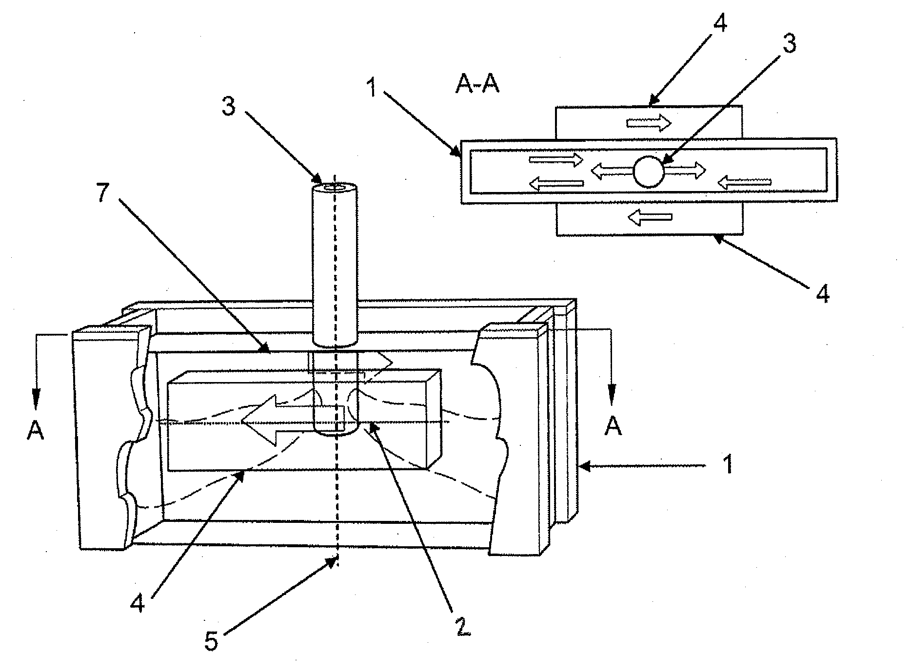
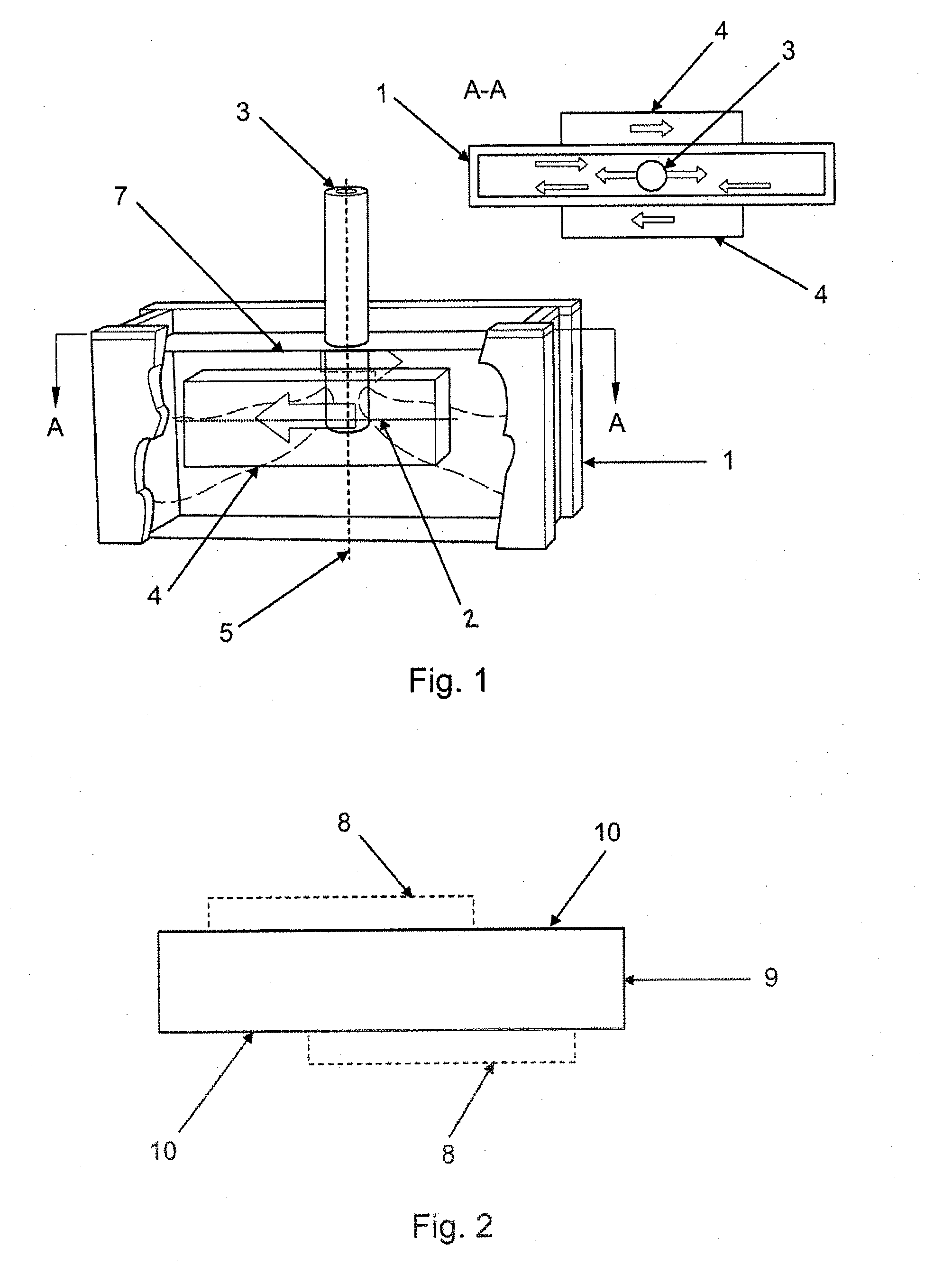
[0023]FIG. 1 shows an explanatory sketch of the invention, comprising a mould 1 enclosing a melt 2 which is supplied to the mould 1 by means of a casting tube 3 lowered into the melt. The melt 2 is cooled and a partially solidified strand is formed. The strand is then moved continuously out of the mould 1. According to the invention, at least one stirrer 4 is arranged which has an iron core and a coil applied around it and, with the iron cores arranged so as not to cover the whole length of the broad sides of the mould but instead at least 50% of the broad sides of the mould and at most 80% of the broad sides of the mould, symmetrically about the centre line 5 of the mould 1 on both sides of the broad sides of the mould. The iron cores are arranged such that their upper parts are positioned at a distance from the meniscus that lies from 50 mm above the surface 7 of the meniscus to 195 mm below said surface 7, ...


PUM

PropertyMeasurementUnit
distanceaaaaaaaaaa
distanceaaaaaaaaaa
distanceaaaaaaaaaa

Abstract

A method for casting of metal. A mold is provided including two broad sides and two narrow sides. A molten metal is introduced into the mold. There is a meniscus at a top of the molten metal. Additional molten metal is supplied into the molten metal via a casting tube below the meniscus. At least one stirrer including an iron core and a coil applied around the iron core is arranged around the mold. A length of the iron core in relation to a length of the broad side of the mold is between 50% and 80% of the length of the broad side. An upper part of the iron core is positioned from 50 mm above to 195 mm below the surface of the meniscus. A magnetic field is applied to the molten metal with the at least one stirrer to stir the molten metal.

Description

CROSS-REFERENCE TO RELATED APPLICATIONS[0001]This application is a divisional application of co-pending U.S. patent application Ser. No. 12 / 298,537 filed 27 Oct. 2008, and claims priority to Swedish patent application number 0600919-5 filed 25 Apr. 2006 and application Ser. No. 12 / 298,537 is the national phase under 35 U.S.C. §371 of PCT / SE2007 / 050269 filed 10 Apr. 2007.TECHNICAL FIELD[0002]The present invention relates to a device for continuous or semicontinuous casting of metals including a stirrer.BACKGROUND OF THE INVENTION AND PRIOR ART[0003]During continuous or semicontinuous casting, a molten metal is supplied to a casting mould, hereinafter designated mould, in which it is cooled and formed into an elongated strand. Depending on its cross-sectional dimensions, the strand is designated BILLET, BLOOM or SLAB. During the casting, a primary flow of hot, molten metal is supplied to the cooled mould, in which the metal is cooled and at least partially solidifies into an elongated...

Claims


Application Information

Patent Timeline
Patent Type & Authority Applications(United States)
IPC IPC(8): B22D27/02B22D11/00
CPCB22D11/115C22C9/00B22D41/08B22D27/02
Inventor KOLLBERG, STENERIKSSON, JAN-ERIK
Owner ABB (SCHWEIZ) AG
Why Eureka
Try Eureka