Agitating device and liquid ejecting apparatus

Active Publication Date: 2012-08-09
SEIKO EPSON CORP
View PDF1 Cites 19 Cited by
  • Summary
  • Abstract
  • Description
  • Claims
  • Application Information

AI Technical Summary

Benefits of technology

[0030]According to the aspect of the invention, since the agitating portion is provided in a part of

Problems solved by technology

In the related art described above, in a case where the liquid is left for a predetermined period or the like, there are problems

Method used


Image

  • Agitating device and liquid ejecting apparatus
  • Agitating device and liquid ejecting apparatus
  • Agitating device and liquid ejecting apparatus

Examples


Example

First Embodiment

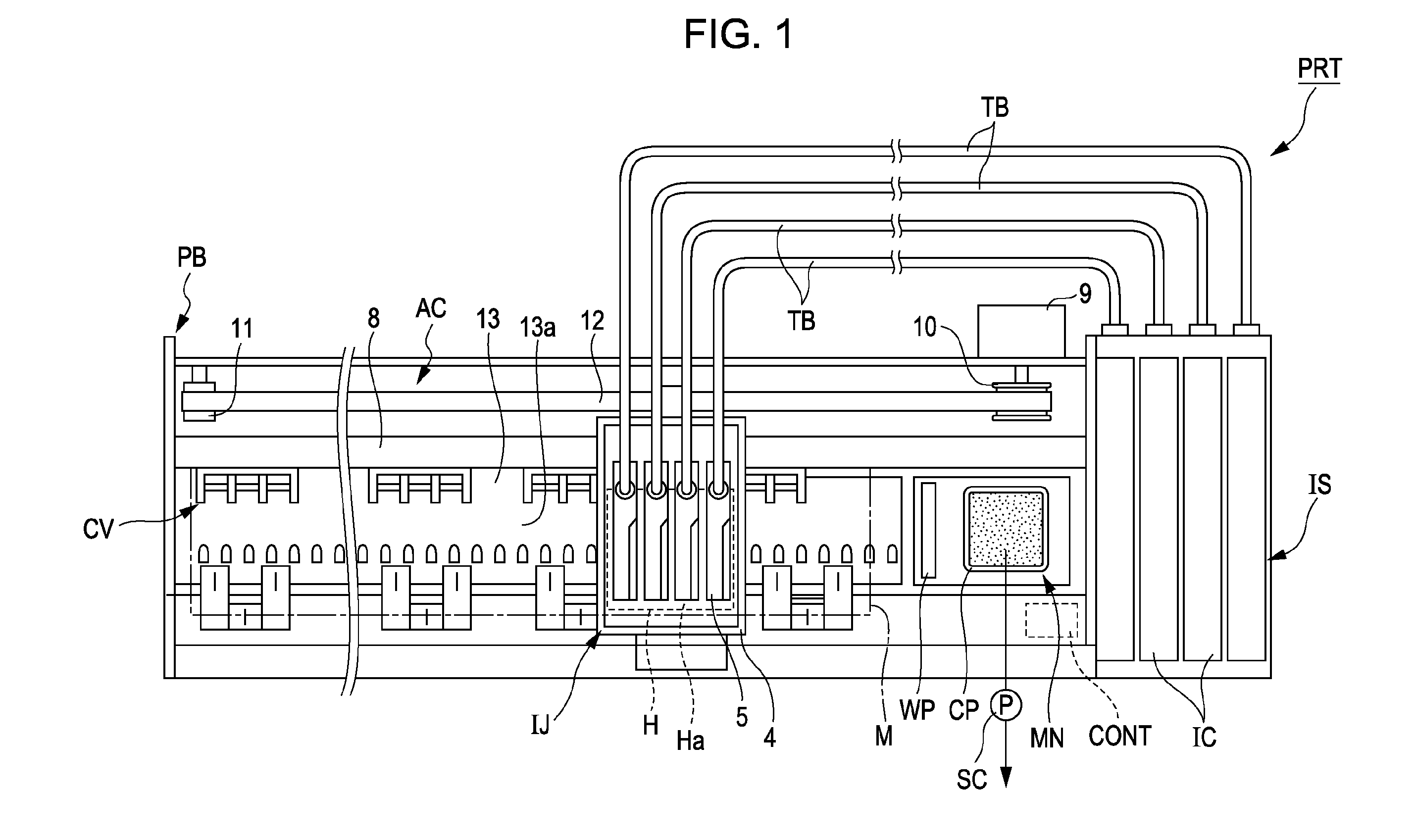
[0043]FIG. 1 is a diagram illustrating a schematic configuration of a printing apparatus PRT (liquid ejecting apparatus) according to a first embodiment of the invention. In this embodiment, as the printing apparatus PRT, an ink jet type printing apparatus is exemplified. Ink cartridges IC are mounted in the printing apparatus PRT.

[0044]The printing apparatus PRT illustrated in FIG. 1 is an apparatus that performs a printing process while transporting a sheet-like medium M such as paper or a plastic sheet. The printing apparatus PRT includes a housing PB, an ink jet mechanism IJ that ejects ink onto the medium M, an ink supply mechanism IS that supplies ink to the ink jet mechanism IJ, a transportation mechanism CV that transports the medium M, a maintenance mechanism MN that performs a maintenance operation of the ink jet mechanism IJ, and a control device CONT that controls the mechanisms.

[0045]The housing PB is formed to have a direction as a longitudinal directio...

Example

Second Embodiment

[0072]Next, a second embodiment of the invention will be described.

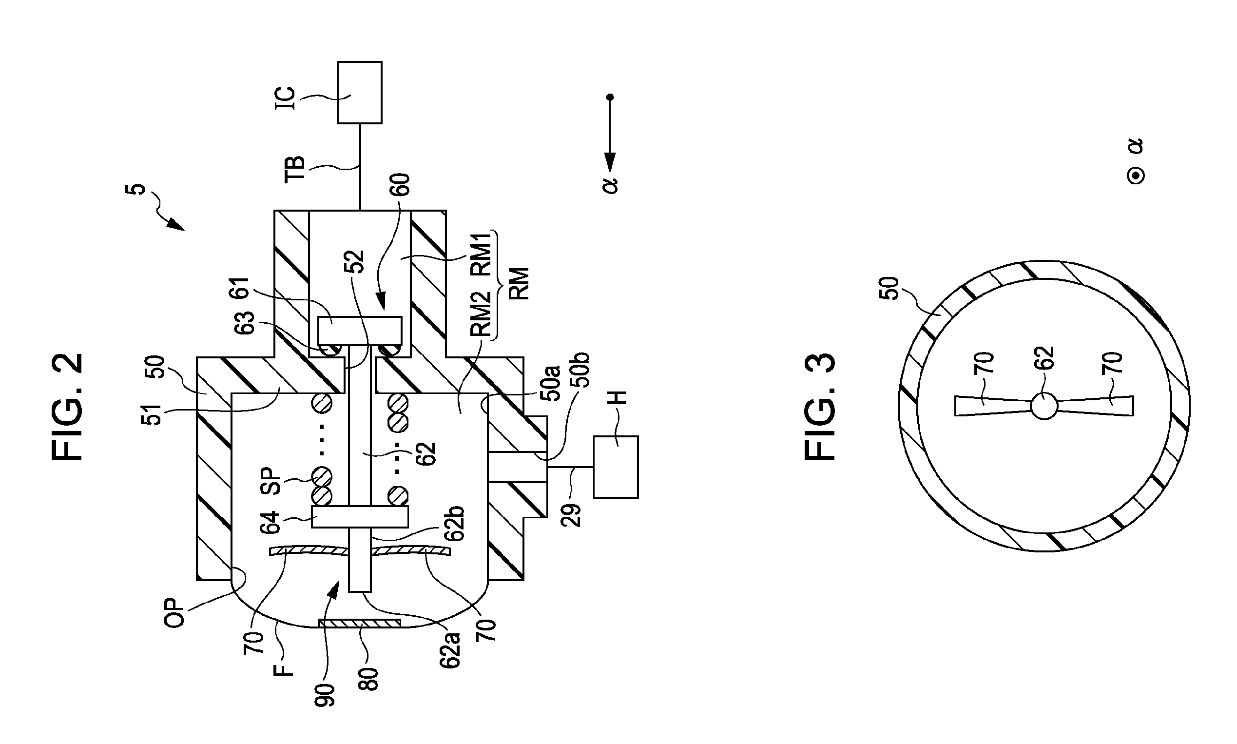
[0073]FIG. 5 is a cross-sectional view illustrating the configuration of a pressure adjustment unit 105 according to this embodiment.

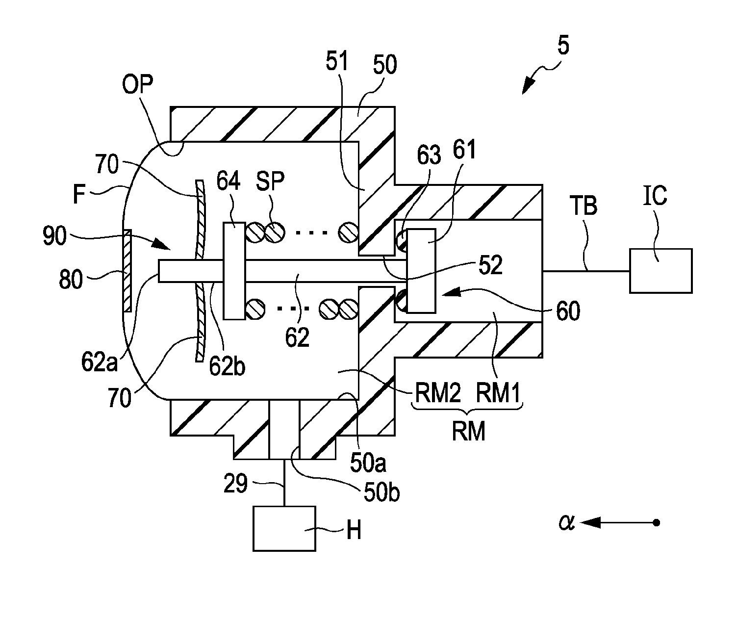
[0074]As illustrated in FIG. 5, the pressure adjustment unit 105 has a protruding portion 170 at the end portion 62a of the shaft portion 62. In this embodiment, an agitating device 190 is constituted by the valve 60 and the protruding portion 170. In FIG. 5, the downward direction in the figure is described as the direction of gravity (a direction in which ink is supplied to the head H from the second chamber RM2).

[0075]The protruding portion 170 extends in the direction of gravity from the end portion 62a of the shaft portion 62 toward the inner wall surface 50a of the accommodation chamber formation member 50. The tip end portion of the protruding portion 170 in the direction of gravity is bent to be parallel to the extension direction of the shaft portion 62 (a bent...


PUM


Abstract

An agitating device includes: a movement portion which is provided in a liquid accommodation portion that has an accommodation chamber accommodating a liquid containing a functional material and a deformation portion that is deformed so as to change a volume of the accommodation chamber, and is moved along with deformation of the deformation portion; and an agitating portion which agitates the liquid in the accommodation chamber along with movement of the movement portion.

Description

BACKGROUND[0001]1. Technical Field[0002]The present invention relates to an agitating device and a liquid ejecting apparatus.[0003]2. Related Art[0004]As a liquid ejecting apparatus that ejects liquid, an ink jet type printing apparatus is known. As the configuration of the ink jet type printing apparatus, a configuration including a pressure adjustment mechanism for temporarily storing ink containing functional materials such as pigments, dyes, resins, fine metal particles, and in a state of suppressing a pressure change in the temporarily stored ink, supplying the ink to a liquid ejecting head is known (for example, refer to JP-A-2010-205022). In the pressure adjustment mechanism, an ink chamber that accommodates the ink is provided.[0005]In the related art described above, in a case where the liquid is left for a predetermined period or the like, there are problems in that components contained in the ink in the ink chamber are precipitated and thus a distribution of density of th...

Claims


Application Information

Patent Timeline
IPC IPC(8): B41J2/175
CPCB41J2/175
Inventor OKINA, TAKUYA
Owner SEIKO EPSON CORP
Why Eureka
Try Eureka