Earphone

a stereophone and earphone technology, applied in the field of stereo earphones, can solve the problems of inability to completely suppress digital processing, lack of versatility of signal processing circuits, and difficulty in incorporating digital signal processing circuits into earphones, so as to suppress the occlusion effect, eliminate a variance of frequency characteristics, and suppress the effect of occlusion

Inactive Publication Date: 2012-08-09
FOSTER ELECTRIC CO LTD
View PDF13 Cites 34 Cited by
  • Summary
  • Abstract
  • Description
  • Claims
  • Application Information

AI Technical Summary

Benefits of technology

[0026]By providing the second sound channel with an attenuation material that makes an adjustment to match a phase delay and a sound pressure level of a reflected sound generated by reflection on the spatial boundary, it becomes possible to generate a sound equivalent to a spatial reflected sound in a suitable phase at a suitable sound pressure level.
[0027]Consequently, it becomes possible to achieve the out-of-head sound localization by perceiving a sense of direction within a space by the earphone alone without requiring a signal processing circuit.
[0028]Also, by making an adjustment in such a manner that a variance of the frequency characteristic caused by the occlusion effect in an external auditory canal is eliminated by providing an attenuation material to the first sound channel, it becomes possible to achieve the out-of-head sound localization by suppressing the occlusion effect in an external auditory canal by the earphone alone without requiring a signal processing circuit.
[0029]Also, by providing a plurality of opening portions each corresponding to an opening end to the driver unit in each of the front surface and the rear surface to eliminate a variance of the frequency characteristic caused by the occlusion effect in an external auditory canal, it becomes possible to achieve the out-of-head sound localization by suppressing the occlusion effect in an external auditory canal by the earphone alone without requiring a signal processing circuit.
[0030]Also, by making an adjustment in such a manner that a variance of the frequency characteristic caused by the occlusion effect in an external auditory canal is eliminated by providing an attenuation material having a selected attenuation characteristic to the opening portion, it becomes possible to achieve the out-of-head sound localization by suppressing the occlusion effect in an external auditory canal by the earphone alone without requiring a signal processing circuit.

Problems solved by technology

When such a digital signal processing circuit is used, it is difficult to incorporate the digital signal processing circuit into an earphone and it becomes necessary to separately provide an apparatus, such as an exclusive-use headphone amplifier.
Accordingly, there arise other problems that it is tedious to find a place to install the signal processing circuit and prepare a power supply and that the signal processing circuit lacks versatility.
There is still another problem that even digital processing cannot completely suppress deterioration during signal processing.

Method used


Image

  • Earphone
  • Earphone
  • Earphone

Examples


embodiment

Configuration of Embodiment

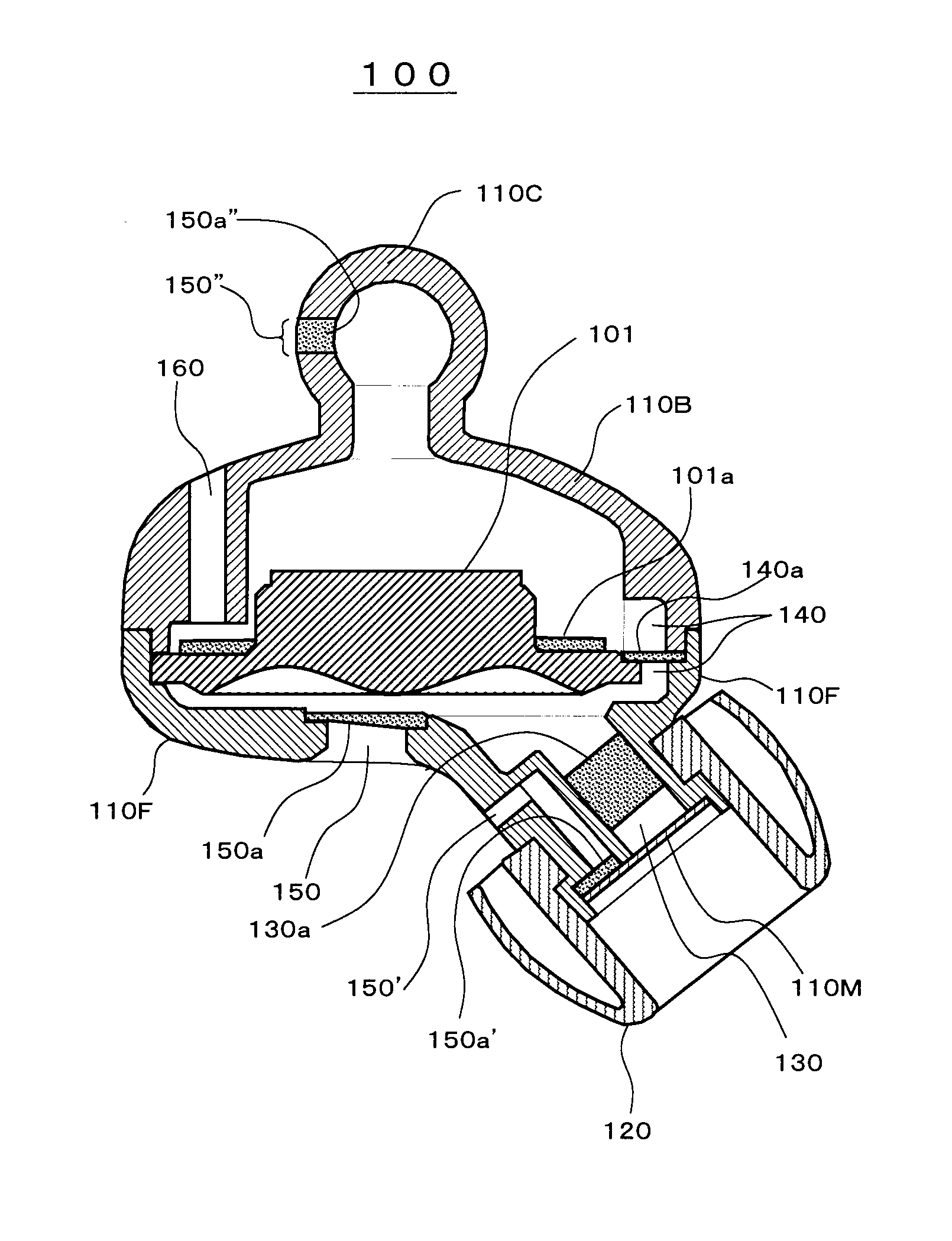
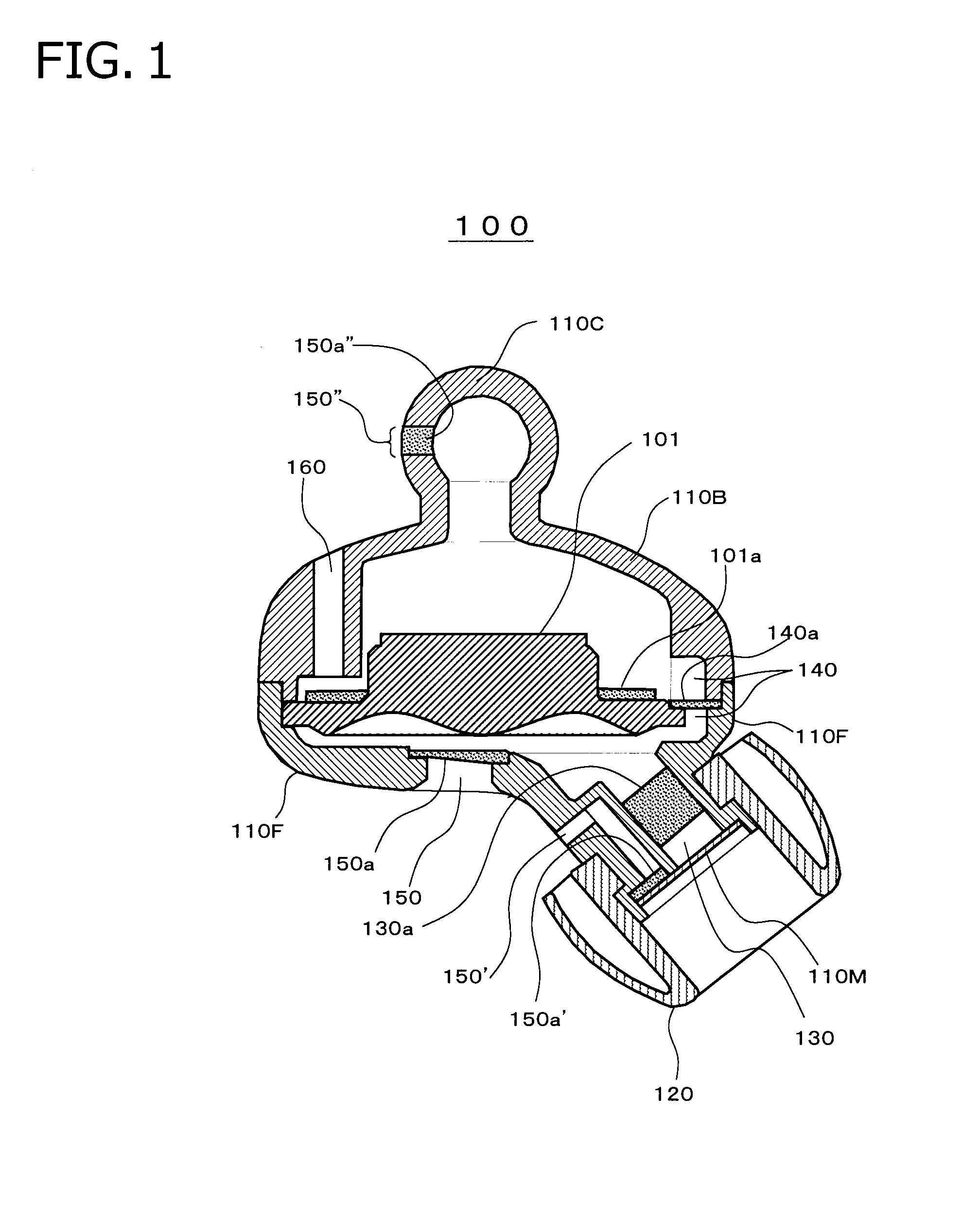
[0035]FIG. 1 is a view showing a sectional configuration of an earphone 100 according to an embodiment of the invention.

[0036]Referring to FIG. 1, a driver unit 101 that generates a sound by vibrating a vibration plate according to an electric signal inputted therein is installed at a center, and installed on the outside of the driver unit 101 are a front housing 110F as a first sound channel provided as a sound exit and a front enclosure, a back housing 110B provided as a rear enclosure while securing a rear space, and a cable housing 110C provided to secure a rear space and for extraction of cables. Also, an attenuation material 101a is installed on the rear side of the vibration plate of the driver unit 101 to attenuate a resonance peak of the vibration plate.

[0037]The front housing 110F is provided with a tube-like first sound channel 130 as a sound exit. Further, an ear piece 120 made of silicon rubber or the like so as to be inserted into the entranc...

modification 1

[0055]It should be understood that the respective configurations shown in FIG. 1 merely represent a specific example of the embodiment and various modifications are possible.

[0056]For example, it is possible to provide a plurality of second sound channels as the second sound channel 140 to generate a sound equivalent to a plurality of spatial reflected sounds each having a different time lag.

[0057]In this case, a time lag can be extended or shortened and magnitude of a delay can be increased or decreased by selectively switching a plurality of the second sound channels to open and close using shutters or the like, so that a user can select a desired reflected sound, such as reverberation in a small hall, reverberation in a large hall, and reverberation in a concert venue.

modification 2

[0058]By forming the attenuation material 130a exchangeable by a user, the user becomes free to make an adjustment regarding to which extent the occlusion effect in an external auditory canal is eliminated (for example, adjustment of an amount of attenuation and a frequency) and a selection regarding to which extent the out-of-head sound localization is widened or narrowed. Likewise, by also forming the other attenuation materials exchangeable by the user, the user becomes free to make an adjustment regarding to which extent the occlusion effect in an external auditory canal is eliminated and a selection regarding to which extent the out-of-head sound localization is widened or narrowed.


PUM


Abstract

an earphone has a driver unit that generates a sound according to an electrical signal inputted therein, a first sound channel from which the sound generated in the driver unit is outputted, and a second sound channel through which a sound generated in the driver unit is transmitted by way of a channel different from the first sound channel to combine the transmitted sound with the sound in the first sound channel.

Description

BACKGROUND OF THE INVENTION[0001]1. Field of the Invention[0002]The present invention relates to a stereo earphone and to a technique of solving a problem that in-head sound localization gives awkwardness and uncomfortable feelings.[0003]2. Description of Related Art[0004]an earphone is configured to generate a sound corresponding to an input signal by generating a compression wave of air using vibrations of a vibration plate in a driver unit installed in a housing. In particular, an insert-type earphone, which directly transmits sounds to the entrance of an external auditory canal by a sound conduit and an ear piece, is advantageous in that efficiency is high and influences of external sounds are small.[0005]With the earphone as above, however, the lack of out-of-head sound localization becomes a problem. More specifically, because sound images are not localized outside the head of a listener but localized in the head of the listener, there arises a problem that the listener percei...

Claims


Application Information

Patent Timeline
Patent Type & Authority Applications(United States)
IPC IPC(8): H04R5/033
CPCH04R1/1016H04R2460/09H04R1/2819
Inventor YAMAGUCHI, FUMIHIKO
Owner FOSTER ELECTRIC CO LTD
Why Eureka
Try Eureka