Heater and image heating apparatus including same

a technology for heating apparatus and image, which is applied in the direction of ohmic-resistance heating, electrographic process, instruments, etc., can solve the problems of difficult to set the total resistance of the heat generation resistive member in one heater within a range that can be used with a commercial power supply, and achieve the effect of suppressing heat generation distribution unevenness

Active Publication Date: 2012-08-09
CANON KK
View PDF9 Cites 47 Cited by
  • Summary
  • Abstract
  • Description
  • Claims
  • Application Information

AI Technical Summary

Benefits of technology

[0007]The present invention enables suppression of heat generation distribution unevenness in a heater longitudinal direction.
[0008]Further fe...

Problems solved by technology

If the non-sheet feeding portion has an excessively high temperature, parts in the apparatus may be damaged, and if printing is performed on a large-size sheet in a state in which a non-sheet feeding portion temperature increase has occurred, hot offset of toner may occur in areas corr...

Method used


Image

  • Heater and image heating apparatus including same
  • Heater and image heating apparatus including same
  • Heater and image heating apparatus including same

Examples


embodiment 1

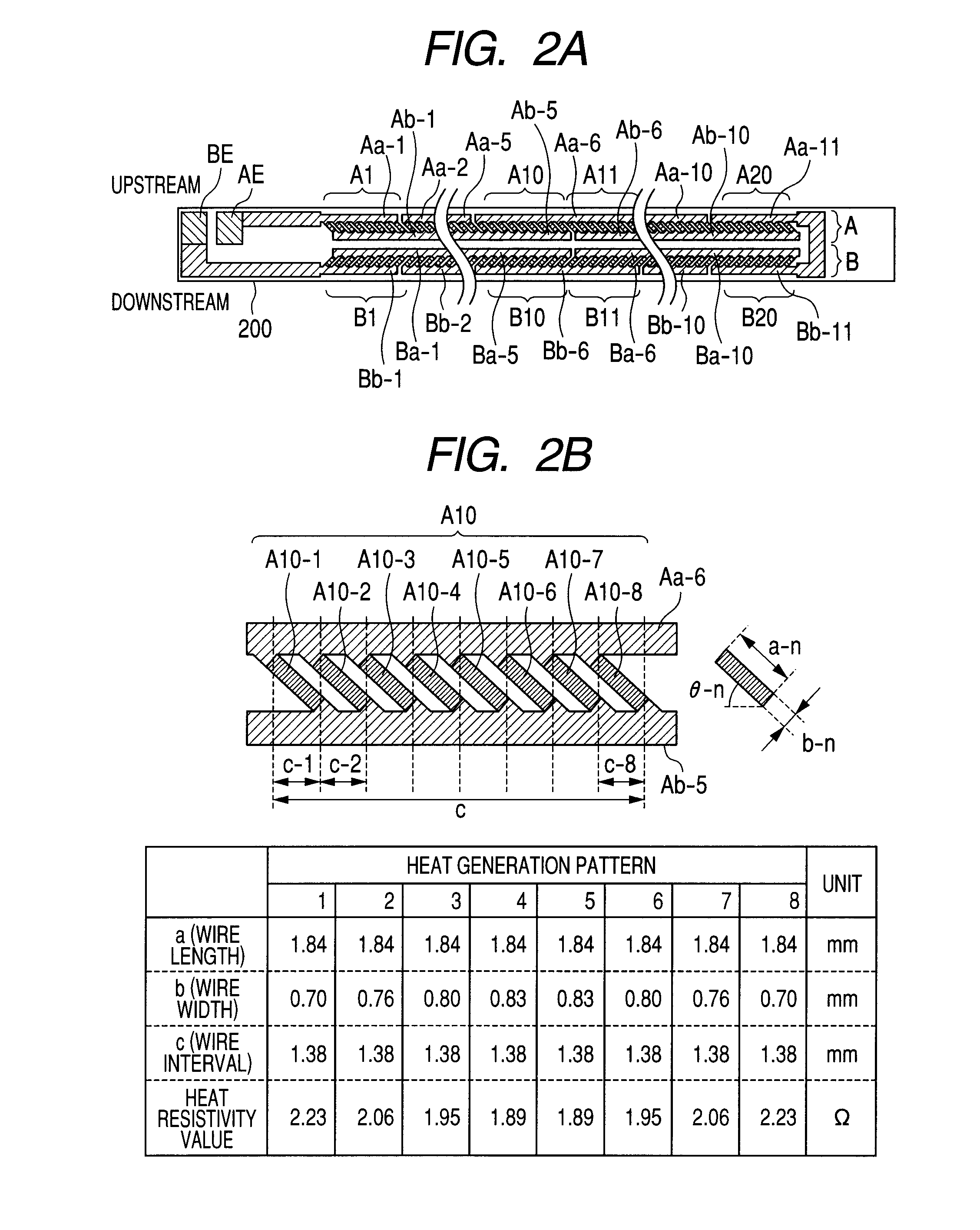
[0026]FIGS. 2A to 2C are diagrams for describing the structure of a heater. FIG. 2A is a plan view of a heater, FIG. 2B is an enlarged view illustrating a heat generation block A10 in a heat generation line A, and FIG. 2C is an enlarged view illustrating a heat generation block A11 in the heat generation line A. Both heat generation resistive members in the heat generation line A and heat generation resistive members in the heat generation line B are PTC heat generation resistive members.

[0027]The heat generation line A (first line) includes 20 heat generation blocks A1 to A20, and the heat generation blocks A1 to A20 are connected in series. The heat generation line B (second line) also includes 20 heat generation blocks B1 to B20, and the heat generation blocks B1 to B20 are also connected in series.

[0028]Furthermore, the heat generation line A and the heat generation line B are electrically connected in series. Power is supplied to the heat generation lines A and B from electrode...

embodiment 2

[0069]Next, Embodiment 2 in which changes have been made to a heater to be installed in an image heating apparatus will be described. A description of components similar to those in Embodiment 1 will be omitted.

[0070]FIG. 8 is a diagram illustrating a configuration of a heater 800 in Embodiment 2. The heater 800 is configured so that a heat generation line A (first line) and a heat generation line B (second line) can separately be driven by two heater drive circuits, and for that purpose, an electrode CE is added to the heater 200 in Embodiment 1 between the heat generation lines A and B. Power is supplied to the heat generation line A via an electrode AE and the electrode CE, and power is supplied to the heat generation line B via electrode BE and the electrode CE. The configuration is the same as that of the heater 200 except the addition of the electrode CE.

[0071]As described above, the present invention can also be applied to a heater configured so that heat generation lines A a...

embodiment 3

[0072]Next, Embodiment 3 in which changes have been made to a heater to be installed in an image heating apparatus will be described. A description of components similar to those in Embodiment 1 will be omitted.

[0073]FIGS. 9A to 9C are configurations of a heater 900 in Embodiment 3. The heater 900 is configured to include only the heat generation line A (first line) in the heater 200, and includes electrodes AE1 and AE2. Power is supplied to the heat generation line A via the electrode AE1 and the electrode AE2. The method for providing an even heat generation distribution in the heater longitudinal direction, which has been described for the heater 200 in Embodiment 1, can be used for the case where there is only one heat generation line.

[0074]FIG. 9B is a detailed diagram of a heat generation block A1 in the heater 900. In the heat generation block A1, eight heat generation resistive members, i.e., from a heat generation resistive member A1-1 with a line length a-1, a line width b...


PUM


Abstract

The image heating apparatus includes a heater that achieves even heat-generation distribution and suppression of a non-sheet feeding portion temperature increase when an image is printed on a sheet whose size is smaller than a maximum size for the apparatus, and an endless belt, wherein plural heat-generation resistive members having positive temperature coefficients are connected in parallel are provided between first and second conductive members provided along a longitudinal direction of a substrate; plural heat-generation blocks including the plural heat-generation resistive members connected in parallel, are arranged in series along the longitudinal direction; and in the plural heat-generation resistive members included in one of the heat-generation blocks, a heat-generation resistive member arranged at an end portion in the longitudinal direction has a resistivity value higher than that of a heat generation resistive member arranged at a center in the longitudinal direction, or an interval between heat generation resistive members is larger in the end portion.

Description

TECHNICAL FIELD[0001]The present invention relates to a heater that can favorably be used in a heat fixing apparatus to be installed in an image forming apparatus such as an electrophotographic copier or an electrophotographic printer, and an image heating apparatus including the heater.BACKGROUND ART[0002]Embodiments of a fixing apparatus to be installed in a copier or a printer include an endless belt, a ceramic heater that is in contact with an inner surface of the endless belt, and a pressure roller forming a fixing nip portion together with the ceramic heater through the endless belt. Upon performing continuous printing on a small-size sheet with an image forming apparatus including the fixing apparatus, the phenomenon of a gradual temperature increase in portions in the longitudinal direction of the fixing nip portion in which the sheet is not fed (non-sheet feeding portion temperature increase) occurs. If the non-sheet feeding portion has an excessively high temperature, part...

Claims


Application Information

Patent Timeline
IPC IPC(8): G03G15/20H05B3/02
CPCG03G2215/2035H05B3/0095G03G15/2042H05B3/46G03G15/2053H05B3/26
Inventor SHIMURA, YASUHIRONIHONYANAGI, KOJI
Owner CANON KK
Why Eureka
Try Eureka