Light-emitting diode drive device and light-emitting diode illumination control method
A technology for light-emitting diodes and driving devices, applied in the field of light-emitting diode driving devices and lighting control of light-emitting diodes, can solve the problems of performance degradation, easy noise generation, residual unconsumed power, etc.
- Summary
- Abstract
- Description
- Claims
- Application Information
AI Technical Summary
Problems solved by technology
Method used
Image

Examples
Embodiment 1
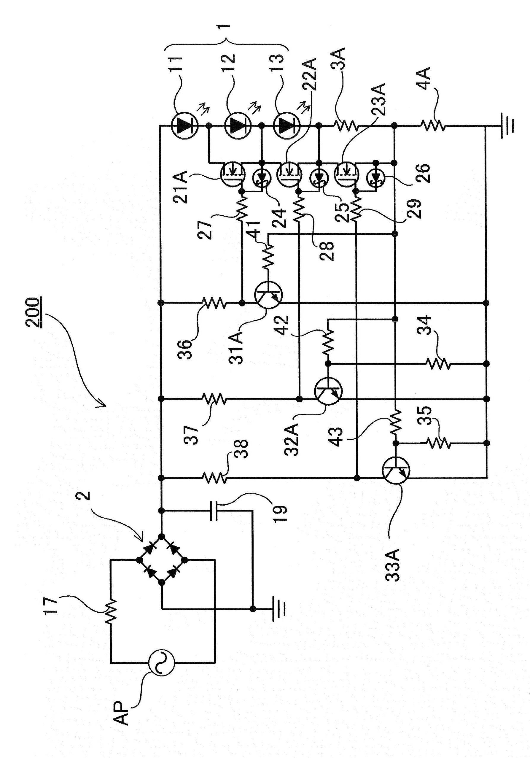
[0061] Next, as Example 1, in figure 2 is shown using semiconductor components to achieve figure 1 A specific circuit configuration example of the structure. In the light emitting diode driving device 200 shown in the figure, a diode bridge is used as the rectification circuit 2 connected to the AC power supply AP. Furthermore, a protection resistor 17 is provided between the AC power supply AP and the rectification circuit 2 . Furthermore, a bypass capacitor 19 is connected to the output side of the rectifier circuit 2 .
[0062] (AC Power AP)
[0063] AC power supply AP can properly use 100V commercial power supply. 100V of this commercial power supply is an effective value, and the maximum voltage of the rectified waveform after full-wave rectification is about 141V.
[0064] (LED block)
[0065] Each LED block is connected in series with each other, and is divided into a plurality of blocks, and a terminal is drawn from the boundary between blocks, and is connected...
Embodiment 2
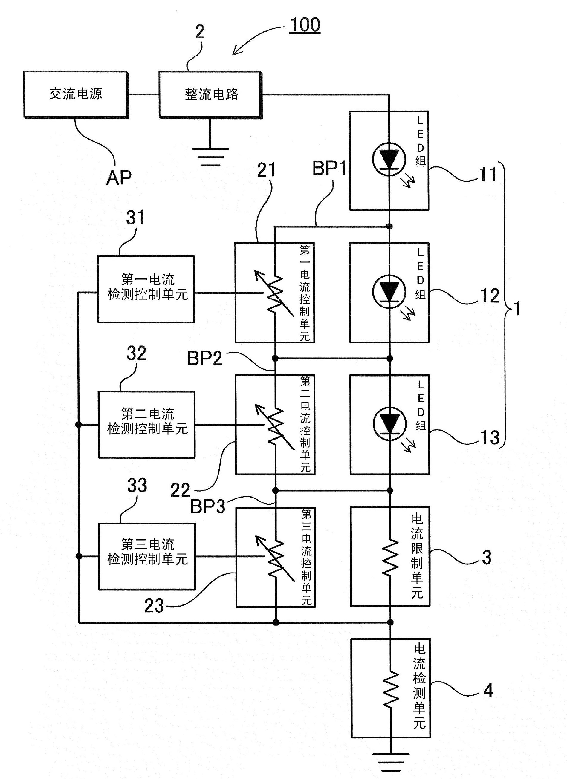
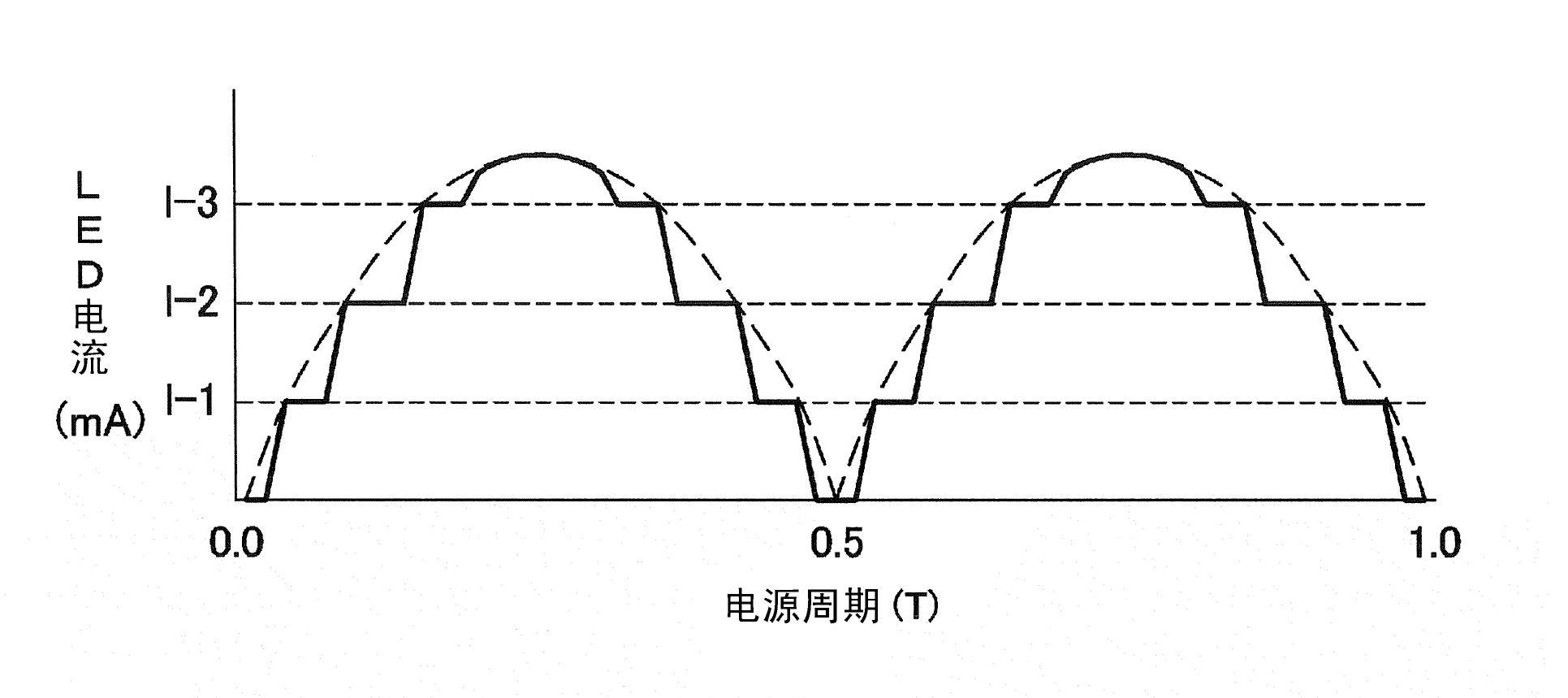
[0099] The above operation is control in consideration of the power factor. especially in figure 2 In the circuit example of , since the LED block group 1 is connected in series with one line, by performing constant current control on each LED block with a different current value, as image 3 Make the current waveform into a step shape as shown in the curve of . On the other hand, as Example 2, Figure 4 The voltage waveform is indicated using the figure 2 An example of a circuit that places more emphasis on utilization efficiency than power factor. In this control example, with image 3 Compared with the example of the above example, the resistance value and the like are set so that the constant current control of each LED block is close to each other, and the output is increased by increasing the overall current amount, and brighter illumination light is obtained. as Figure 4 In the LED current waveform shown, the measured values of the circuit constants are power...
Embodiment 3
[0101] In the above example, the LED current detection resistor is made common to each LED block or the like. That is, each current detection control unit performs control based on the current amount of the common current detection unit, and the circuit configuration can be simplified. However, it is also possible to employ a configuration in which LED current detection resistors are individually provided for each LED block or the like. As Example 3, in Figure 5 An example of this is shown in the circuit diagram. In the light emitting diode driving device 300 shown in the figure, the basic structure and operation are substantially the same as those of the first embodiment, and LED current detection resistors are provided for each of the three LED blocks. Specifically, the current detection of the second LED block 12 is performed by the first LED current detection resistor 4B, the current detection of the third LED block 13 is performed by the second LED current detection re...
PUM
| Property | Measurement | Unit |
|---|---|---|
| Electrostatic capacitance | aaaaa | aaaaa |
| Luminous efficiency | aaaaa | aaaaa |
Abstract
Description
Claims
Application Information